background image

98

1.877.877.2269

BLACKBOX.COM

NEED HELP?

LEAVE THE TECH TO US

LIVE 24/7

TECHNICAL

SUPPORT

1.877.877.2269

CHAPTER 4: CONFIGURATION

OSD

Š

Š

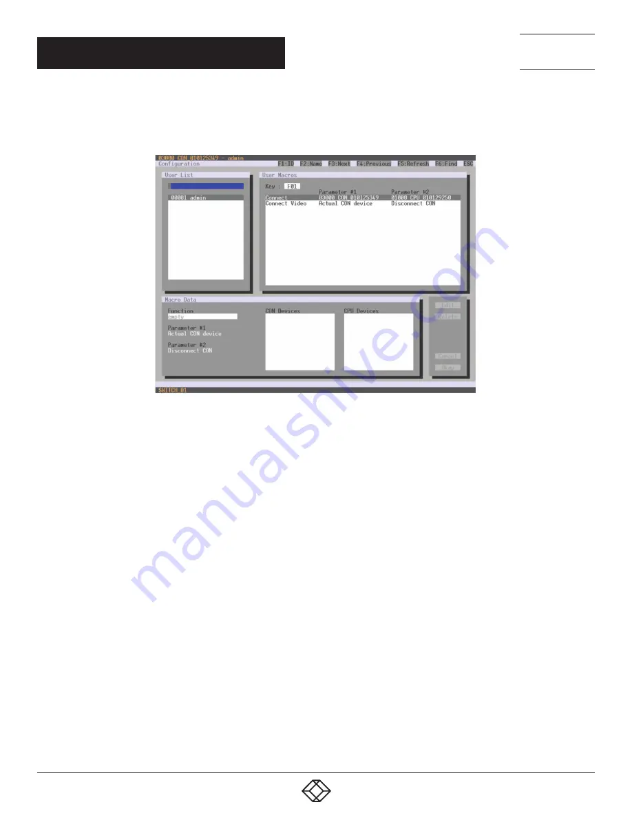
Select Configuration > User Macros in the main menu and select the user for which a user macro will be created.

FIGURE 4-27.  CONFIGURATION—USER MACROS

To create a macro for the selected user, proceed as follows:
1. Select in the Key field the function key (F1–F16) for which a macro has to be created.
2. Select the position in the Key list where a macro command is to be inserted.
3. Select a macro command in the Macro Data field.
4. Set the necessary parameters P1 and P2 (e.g., CON Devices or CPU Devices) for the selected macro command.
5. Confirm your selection by pressing <Enter> and repeat the process for further macro commands, if necessary.

Summary of Contents for ACXC16

Page 1: ...24 7 TECHNICAL SUPPORT AT 1 877 877 2269 OR VISIT BLACKBOX COM COMPACT KVM MATRIX SWITCHES DKM FXC SWITCH SERIES USER MANUAL...

Page 2: ...2 5 Options 15 2 6 Device Views 16 2 6 1 80 Port Chassis Models ACXC80 ACXC80F ACXC80FHS ACXC48F32 16 2 6 2 64 Port Chassis Models ACXC64 ACXC64F ACXC64FHS ACXC48F16 18 2 6 3 48 Port Chassis Models A...

Page 3: ...3 Assignment 68 4 3 1 Virtual CPU 68 4 3 2 Virtual Console 70 4 4 System Settings 72 4 4 1 System Data 72 4 4 2 Automatic ID 75 4 4 3 Access 78 4 4 4 Switch 80 4 4 5 Network 84 4 4 6 Date and Time 88...

Page 4: ...4 16 2 Extender Update 149 4 17 License Management 152 5 OPERATION 153 5 1 Operation via Hotkeys 153 5 1 1 Direct Switching 153 5 1 2 Scan Mode 154 5 1 3 Function Keys F1 F6 155 5 1 4 Addressing of M...

Page 5: ...8 TECHNICAL SUPPORT 175 8 1 Support Checklist 175 8 2 Shipping Checklist 175 9 REGULATORY INFORMATION 176 9 1 FCC Statement 176 9 2 CE Declaration of Conformity 176 9 3 Product Safety 176 9 4 WEEE 176...

Page 6: ...se ensure that the ground connection is maintained from the outlet socket through to the power supply s AC power input In case the device is equipped with one or more grounding screws be sure to use t...

Page 7: ...connectors at both ends All four cable wire pairs are used 1 2 INTERCONNECT CABLE CATX NOTE A point to point connection is required Operation with several patch fields is possible Routing over an act...

Page 8: ...TABLE CABLE LENGTHS CABLE TYPE LENGTH CATx Solid Core Cable AWG24 400 ft 140 m CATx Patch Cable AWG26 8 200 ft 70 m 1 3 CONNECTOR PINOUTS TABLE 1 3 RJ 45 SERIAL PICTURE PIN SIGNAL PIN SIGNAL 1 DCD 5 R...

Page 9: ...E ACXC80 ACXC80F ACXC80FHS 125 W max ACXC48F32 125 W max ACXC64 ACXC64F ACXC64FHS 105 W max ACXC48F16 105 W max ACXC48 ACXC48F ACXC48FHS ACXC48U 90 W max ACXC32 ACXC32F ACXC32FHS ACXC32U 65 W max ACXC...

Page 10: ...16 Matrix 3 5 H x 17 4 W x 17 1 D 9 x 44 3 x 43 5 cm Shipping Box 7 9 H x 23 7 W x 20 7 D 20 x 60 2 x 52 6 cm ACXC48 ACXC48F ACXC48FHS ACXC48U Matrix 1 8 H x 17 4 W x 17 1 D 4 5 x 44 3 x 43 5 cm Shipp...

Page 11: ...1 1 lb 9 6 kg ACXC64 ACXC64F ACXC64FHS Matrix 15 4 lb 7 0 kg Shipping Box 20 7 lb 9 4 kg ACXC48F16 Matrix 15 4 lb 7 0 kg Shipping Box 20 7 lb 9 4 kg ACXC48 ACXC48F ACXC48FHS ACXC48U Matrix 9 0 lb 4 1...

Page 12: ...000 238 000 ACXC64FHS 92 900 280 000 238 000 ACXC48 140 000 280 000 295 700 ACXC48F 133 400 280 000 295 700 ACXC48FHS 133 400 280 000 295 700 ACXC48U 133 400 280 000 295 700 ACXC32 165 300 280 000 295...

Page 13: ...KVM Matrix Switch is designed to operate with extenders that are able to transmit video KVM and USB 2 0 signals But it can also be used as a video matrix The connection between the matrix and the peri...

Page 14: ...deo devices where used as a video matrix CPU Units are connected directly to the sources computer CPU by the provided cables Monitor s keyboard and mouse are connected to the CON Units Communication b...

Page 15: ...ower supply unit ACXC32FHS Compact KVM Matrix Switch with 32 ports 2 5 Gbit s transmission bandwidth redundant power supply unit ACXC32U Compact KVM Matrix Switch with 32 universal ports fiber redunda...

Page 16: ...Switch illustrate the various available chassis types 2 6 1 80 PORT CHASSIS MODELS ACXC80 ACXC80F ACXC80FHS ACXC48F32 FIGURE 2 2 80 PORT CHASSIS OPTIONS FRONT VIEWS TABLE 2 5 80 PORT CHASSIS FRONT VI...

Page 17: ...LIVE 24 7 TECHNICAL SUPPORT 1 877 877 2269 CHAPTER 2 OVERVIEW FIGURE 2 3 80 PORT CHASSIS BACK VIEW TABLE 2 6 80 PORT CHASSIS BACK VIEW COMPONENTS NUMBER IN FIGURE 2 3 COMPONENT 1 Connect to power sup...

Page 18: ...VIEW 2 6 2 64 PORT CHASSIS MODELS ACXC64 ACXC64F ACXC64FHS ACXC48F16 FIGURE 2 4 64 PORT CHASSIS OPTIONS FRONT VIEWS TABLE 2 7 64 PORT CHASSIS FRONT VIEW COMPONENTS NUMBER IN FIGURE 2 4 COMPONENT 1 I O...

Page 19: ...LIVE 24 7 TECHNICAL SUPPORT 1 877 877 2269 CHAPTER 2 OVERVIEW FIGURE 2 5 64 PORT CHASSIS BACK VIEW TABLE 2 8 64 PORT CHASSIS BACK VIEW COMPONENTS NUMBER IN FIGURE 2 5 COMPONENT 1 Connect to power sup...

Page 20: ...PONENT 1 I O ports 1 16 2 I O ports 17 32 3 I O ports 33 48 4 Serial connection RJ 45 5 Network connection RJ 45 FIGURE 2 7 48 PORT CHASSIS BACK VIEW TABLE 2 10 48 PORT CHASSIS BACK VIEW COMPONENTS NU...

Page 21: ...PORT CHASSIS OPTIONS FRONT VIEWS TABLE 2 11 32 PORT CHASSIS FRONT VIEW COMPONENTS NUMBER IN FIGURE 2 8 COMPONENT 1 I O ports 1 16 2 I O ports 17 32 3 Serial connection RJ 45 4 Network connection RJ 45...

Page 22: ...2 10 16 PORT CHASSIS OPTIONS FRONT VIEWS TABLE 2 13 16 PORT CHASSIS FRONT VIEW COMPONENTS NUMBER IN FIGURE 2 10 COMPONENT 1 I O ports 1 16 2 Serial connection RJ 45 3 Network connection RJ 45 FIGURE 2...

Page 23: ...ASSIS FRONT VIEW COMPONENTS NUMBER IN FIGURE 2 12 COMPONENT 1 I O ports 1 8 2 Serial connection RJ 45 3 Network connection RJ 45 4 Connect to power supply 5 Connect to 5 VDC power supply redundancy op...

Page 24: ...shown at right TABLE 2 17 STATUS LEDS NUMBER IN FIGURE 2 14 COMPONENT 1 Status LED 2 2 Status LED 1 TABLE 2 18 CPU STATUS LEDS FUNCTIONS NUMBER IN FIGURE 2 14 LED STATUS DESCRIPTION 1 Status LED 2 Whi...

Page 25: ...work available OFF No connection to network 2 Status 2 green Flashing Data traffic active OFF Data traffic not active I O PORTS FIGURE 2 16 STATUS LEDS I O PORTS FRONT VIEW TABLE 2 20 STATUS LEDS NUMB...

Page 26: ...IT FRONT VIEW TABLE 2 22 STATUS LEDS NUMBER IN FIGURE 2 17 COMPONENT 1 Power Supply Unit 1 Status LED 2 Power Supply Unit 2 Status LED TABLE 2 23 STATUS LEDS AT THE PORTS OF THE POWER SUPPLY UNITS NUM...

Page 27: ...status LED 1 2 Left fan status LED 2 3 Right fan status LED 2 4 Right fan status LED 1 TABLE 2 25 STATUS LEDS OF THE FAN TRAYS NUMBER IN FIGURE 2 18 LED STATUS DESCRIPTION 1 Left fan status 1 red ON...

Page 28: ...ons and the switching status between the various consoles and CPUs are shown in this menu You have the following option to access the menu JAVA TOOL The current port configuration of the Compact KVM M...

Page 29: ...CHAPTER 2 OVERVIEW FIGURE 2 20 STATUS MATRIX VIEW EXAMPLE 2 The colors indicate the connection status TABLE 2 26 STATUS LEDS COLOR IN FIGURES 2 19 AND 2 20 DESCRIPTION Gray Port not connected Yellow V...

Page 30: ...itched to a CON Unit in Private Mode Port connected to a CON Unit Port connected to a CON Unit with Shared Access to a CPU P Port is connected to a CON Unit that is connected to a CPU Unit in Private...

Page 31: ...e CPU at this port Press the left mouse button to show the extender information of the currently selected port on the right hand side of the working area The following information is available TABLE 2...

Page 32: ...nnections and the switching status between the various CON and CPU Devices are shown within the Matrix Grid The port view is divided into the different Grid matrices As a result each matrix is display...

Page 33: ...2 OVERVIEW NOTE Functions colors and symbols used in the Grid Port View are identical to those in the port status of the Matrix View 2 7 4 EXTENDER OSD All extenders used with the Compact KVM Matrix...

Page 34: ...hed off extenders or insufficiently available Grid lines in Matrix Grid operation ACCESS Full Access Console has a KVM connection to the displayed CPU Video Access Console has a video only connection...

Page 35: ...TABLE 2 31 NETWORK CONFIGURATION FIELD DESCRIPTION DHCP Information whether the network settings are applied dynamically Display Y Yes or N No IP Address Information about the IP address as provided m...

Page 36: ...t Status Network in the task area FIGURE 2 24 STATUS MATRIX VIEW 2 Use the left mouse button to click on the network port of the CPU board The corresponding network status will be shown on the right h...

Page 37: ...n in this menu You have the following options to access the menu OSD The following information is shown in this menu TABLE 2 32 FIRMWARE STATUS INFORMATION FIELD DESCRIPTION Name Description of module...

Page 38: ...tatus of the matrix and store it locally file extension zip select Matrix Save Status or press the respective button in the symbol bar The various modules can expanded and retracted in the Name column...

Page 39: ...ou have the following option to access the menu The following information is shown in this menu TABLE 2 33 FIRMWARE STATUS OF CONNECTED EXTENDERS INFORMATION FIELD DESCRIPTION Name Description of firm...

Page 40: ...nu This function is used for diagnostic purposes You have the following option to request various trace views in the menu OSD The following information is shown in this menu TABLE 2 34 TRACE FUNCTION...

Page 41: ...u have the following option to access the menu To start Syslog Monitoring proceed as follows Select the Monitoring symbol in the symbol bar FIGURE 2 28 MONITORING SYSLOG Logging of system activities s...

Page 42: ...m log file size a new log file will be created When reaching the maximum number of log files the oldest one will be overwritten with the new information FILTER FUNCTION To filter relevant messages out...

Page 43: ...own in the Syslog press the Clear trace button To stop recording messages press the Pause button To continue press the button again 2 10 SNMP The SNMP function allows all function critical and safety...

Page 44: ...on the permission for an active query of the SNMP agent is granted To configure an SNMP server proceed as follows Select Configuration SNMP in the main menu Set the Enable Traps option to Y Yes within...

Page 45: ...lished link between extender and matrix Remove Extender Notification about a removed extender from the matrix notification about a switched off extender notification about an interrupted link between...

Page 46: ...vating this option the permission for an active query of the SNMP agent is granted To configure an SNMP server proceed as follows Select Configuration Network in the task area Activate the Enable Trap...

Page 47: ...Ext Units CPU Devices CON Devices User System Configuration Matrix Grid The following notification levels can be shown TABLE 2 38 NOTIFICATION LEVELS LEVEL DESCRIPTION OK green System Check completed...

Page 48: ...all matrices or SNMP boards that are located in the same subnetwork This is useful for example if the IP address of a specific matrix is unknown and should be accessed via IP You have the following op...

Page 49: ...UPPORT 1 877 877 2269 CHAPTER 2 OVERVIEW NOTE You can use the last column of the Device Finder to access the respective matrix directly using the Connect button To start the Device Finder proceed as f...

Page 50: ...n OSD via keyboard command hotkey o and log in with administrator rights in the main menu under configuration see Section 4 2 1 5 Configure initially as requested NOTE After you configure the system w...

Page 51: ...ompact KVM Matrix Switch can be configured as a Single Head work station a part as Dual Head as Quad Head or even as a video matrix for example In addition to that there are configurations with KVM an...

Page 52: ...another user FIGURE 3 1 KVM MATRIX INSTALLATION EXAMPLE TABLE 3 1 SINGLE HEAD KVM MATRIX INSTALLATION COMPONENTS NUMBER IN FIGURE 3 1 COMPONENT 1 Source computer CPU 2 CPU Unit 3 Interconnect cable 4...

Page 53: ...ion 4 4 1 All other matrices are defined as Sub Matrices Sub matrices must be connected to the master matrix via a network connector RJ 45 on the CPU board The Enable LAN Echo option has to be activat...

Page 54: ...onfiguration it can consist of up to 16 matrices To build a matrix grid the grid matrices are interconnected by Grid Lines In this case the slave matrices can be connected directly to the master matri...

Page 55: ...55 1 877 877 2269 BLACKBOX COM NEED HELP LEAVE THE TECH TO US LIVE 24 7 TECHNICAL SUPPORT 1 877 877 2269 CHAPTER 3 INSTALLATION FIGURE 3 3 MATRIX GRID INSTALLATION EXAMPLE...

Page 56: ...oard commands to enter and to exit Command Mode and to change the Hotkey sequence TABLE 4 1 KEYBOARD COMMANDS FUNCTION KEYBOARD COMMAND Enter Command Mode default 2x Left Shift or Hotkey Exit Command...

Page 57: ...nder press the key combination Right Shift Del within 5 seconds after switching on the CON Unit or plugging in a keyboard To delete the Hotkey for direct OSD access use the following keyboard sequence...

Page 58: ...tion is enabled in the Configuration menu the selection list for switching CPU devices will be opened initially To skip this list press the F7 key LEAVING OSD Press Esc in the main menu or simultaneou...

Page 59: ...fields between two conditions e g between ON OFF or Y Yes N No Space In menus with input fields Save data In menus Select menu item Enter In menus with input fields Cancel data input without saving I...

Page 60: ...e able to set configurations FIGURE 4 2 LOGIN Access to the configuration menu requires administrator rights User login is mandatory TABLE 4 5 LOGIN FIELD INPUT User admin Password admin By pressing F...

Page 61: ...69 or info blackbox com COMPUTER CONNECTION TO THE MATRIX For a direct connection between computer and matrix a cross wired network cable is required For a connection between computer and matrix via s...

Page 62: ...LIVE 24 7 TECHNICAL SUPPORT 1 877 877 2269 CHAPTER 4 CONFIGURATION FIGURE 4 3 CONNECT NOTE Up to twelve connections between the matrix and the Java Tool can be established at the same time due to a l...

Page 63: ...Tool can be activated or deactivated by the checkbox in the upper right corner MOUSE CONTROL You can select the following mouse commands TABLE 4 6 MOUSE COMMANDS FUNCTION MOUSE COMMAND Menu selection...

Page 64: ...t functions are described in the respective chapters To execute a context function use the right mouse button on the corresponding field and select the desired function SORTING FUNCTION Lists and tabl...

Page 65: ...e storage location of the new configuration default or config01 08 in the Select Configuration menu 3 Select Matrix Connect in the menu bar and enter the IP address of the matrix and the name and pass...

Page 66: ...Default Settings tab will open The following default settings parameters can be changed TABLE 4 8 DEFAULT SETTINGS PARAMETERS OPTIONS OPTION DESCRIPTION IP Hostname Default IP address of the matrix re...

Page 67: ...or switching single or all connections available both unidirectional and bidirectional In addition there are telegrams for an overall definition of the total switching status and for saving and loadin...

Page 68: ...tual consoles 4 3 1 VIRTUAL CPU You can assign virtual to real CPUs in this menu With this function the effort of switching several consoles to the same CPU can be reduced If several consoles are conn...

Page 69: ...d virtual CPU 4 Press the Okay button to confirm the assignment The assignment will be made NOTE Only one virtual CPU can be assigned to a real CPU JAVA TOOL Select Assignments Virtual CPU Devices in...

Page 70: ...on menu to check specific settings for the respective console or CPU Use the right mouse button to select the respective console or CPU and select Open CON Device or Open CPU Device 4 3 2 VIRTUAL CONS...

Page 71: ...can be assigned to more than one real console JAVA TOOL Select Assignments Virtual CON Devices in the task area FIGURE 4 10 VIRTUAL CON DEVICES To place an assignment proceed as follows 1 Select the r...

Page 72: ...f the configuration that is used to save the current settings default Standard Info Text Additional text field to describe the configuration default Factory settings Sub Matrix activated If the matrix...

Page 73: ...ivated Synchronize the slave matrix to the switch status of the master matrix deactivated Function not active default Echo Only activated Synchronize the matrix according to the echo of a second matri...

Page 74: ...LIVE 24 7 TECHNICAL SUPPORT 1 877 877 2269 CHAPTER 4 CONFIGURATION OSD Select Configuration System in the main menu FIGURE 4 11 CONFIGURATION SYSTEM You can select the following buttons TABLE 4 12 BU...

Page 75: ...HNICAL SUPPORT 1 877 877 2269 CHAPTER 4 CONFIGURATION JAVA TOOL FIGURE 4 12 SYSTEM DATA 4 4 2 AUTOMATIC ID Settings for automatic creation of CPU and CON Devices when a new extender unit is connected...

Page 76: ...e Numerical value Initial value of the automatic ID for real CPUs default value 1000 ID Virtual CPU Device Numerical value Initial value of the automatic ID for virtual CPUs default value 2000 ID Real...

Page 77: ...77 2269 BLACKBOX COM NEED HELP LEAVE THE TECH TO US LIVE 24 7 TECHNICAL SUPPORT 1 877 877 2269 CHAPTER 4 CONFIGURATION JAVA TOOL Select the Automatic ID tab in System System Data FIGURE 4 14 SYSTEM AU...

Page 78: ...ording to the permissions in the respective Console ACL Access Control List No login required deactivated Function not active Enable new User activated Newly created users automatically receive access...

Page 79: ...LIVE 24 7 TECHNICAL SUPPORT 1 877 877 2269 CHAPTER 4 CONFIGURATION OSD Select Configuration Access in the main menu FIGURE 4 15 CONFIGURATION ACCESS You can select the following buttons TABLE 4 16 BU...

Page 80: ...RT 1 877 877 2269 CHAPTER 4 CONFIGURATION JAVA TOOL Select System Access in the task area FIGURE 4 16 SYSTEM ACCESS 4 4 4 SWITCH The configuration of the switching parameters is set in this menu You h...

Page 81: ...control Force Disconnect has to be deactivated deactivated Function not active default CPU Auto Connect activated If a console is not connected to a CPU you can establish an automatic connection to t...

Page 82: ...LIVE 24 7 TECHNICAL SUPPORT 1 877 877 2269 CHAPTER 4 CONFIGURATION OSD Select Configuration Switch in the main menu FIGURE 4 17 CONFIGURATION SWITCH You can select the following buttons TABLE 4 18 BU...

Page 83: ...3 1 877 877 2269 BLACKBOX COM NEED HELP LEAVE THE TECH TO US LIVE 24 7 TECHNICAL SUPPORT 1 877 877 2269 CHAPTER 4 CONFIGURATION JAVA TOOL Select System Switch in the task area FIGURE 4 18 SYSTEM SWITC...

Page 84: ...Switch activated for access via Java tool API service port 5555 deactivated Function not active FTP Server activated FTP server for transmission of configuration files activated deactivated Function...

Page 85: ...sages are exclusively for matrix diagnostics They only should be activated after consultation with the manufacturer Otherwise increased data traffic might limit the performance of the CPU board INF Ac...

Page 86: ...LIVE 24 7 TECHNICAL SUPPORT 1 877 877 2269 CHAPTER 4 CONFIGURATION OSD Select Configuration Network in the main menu FIGURE 4 19 CONFIGURATION NETWORK You can select the following buttons TABLE 4 20 B...

Page 87: ...trix depending on the configuration and have to be released at the security gateway if necessary The ports only will have to be released if you want to use the respective function TABLE 4 21 NETWORK P...

Page 88: ...s TABLE 4 22 DATE AND TIME SETTINGS FIELD SELECTION DESCRIPTION SNTP Client activated Enable network time server synchronization deactivated Function not active default SNTP Server Byte Input of the S...

Page 89: ...ion to Y Yes 2 Enter the IP address of your SNTP server in the SNTP Server field 3 Select your time zone in the Time Zone field 4 Press the Okay button to confirm your settings 5 Restart the matrix Th...

Page 90: ...ver in the SNTP Server field 3 Select your time zone in the Time Zone field 4 Press the Apply button to confirm your settings 5 Restart the matrix The system time will be now provided by the SNTP serv...

Page 91: ...itive FTP activated Access permission via FTP This setting is necessary for file access from the Java tool or any web browser desactivated Function not active default Power User activated User has use...

Page 92: ...2269 CHAPTER 4 CONFIGURATION OSD Select Configuration User in the main menu FIGURE 4 23 CONFIGURATION USER You can select the following buttons TABLE 4 24 BUTTONS BUTTON FUNCTION New Create a new use...

Page 93: ...user account Cancel Reject changes To configure user access rights for CPUs follow these steps 1 Select a user in the User list 2 Click the right mouse button once on a CPU in one of the respective a...

Page 94: ...ettings You can select the following keyboard commands TABLE 4 26 KEYBOARD COMMANDS FUNCTION KEYBOARD COMMAND Add CPU to Full Access list F Add CPU to Video Access list V Add CPU to No Access list N 4...

Page 95: ...enu FIGURE 4 25 ASSIGNMENTS USER FAVORITES To create a favorite list for your user proceed as follows 1 Select a CPU to be moved to the favorite list on the CPU Devices list Press a to move a CPU Devi...

Page 96: ...e favorite list If you press the button the first eight CPU Devices from the CPU available list will be moved to the favorite list CPU assigned 3 The order of marked CPU Devices within the favorite li...

Page 97: ...user s KVM connection is forwarded to console P1 and is changed to a video only connection Push Video P1 CON The video signal of the current connection KVM or video only is forwarded to console P1 Th...

Page 98: ...To create a macro for the selected user proceed as follows 1 Select in the Key field the function key F1 F16 for which a macro has to be created 2 Select the position in the Key list where a macro com...

Page 99: ...he empty fields 3 Select in the P1 and P2 columns the respective parameters for the macro functions e g corresponding consoles and CPUs 4 Confirm your selections by pressing the Apply button For an ef...

Page 100: ...s an extender unit Dual Head KVM extenders will be recognized as two independent extender units NOTE KVM Extenders automatically create extender units inside the matrix You have the following options...

Page 101: ...ation EXT Units in the main menu FIGURE 4 29 CONFIGURATION EXT UNITS You can select the following buttons TABLE 4 29 BUTTONS BUTTON FUNCTION New Create a new extender unit Edit Edit an existing extend...

Page 102: ...ns TABLE 4 30 BUTTONS BUTTON FUNCTION New Create a new extender unit Delete Delete an existing extender unit Apply Confirm changes of an extender unit Cancel Reject changes FLEXIBLE PORT EXTENDER UNIT...

Page 103: ...EXT Units in the main menu FIGURE 4 31 CONFIGURATION EXT UNITS 1 To configure a USB 2 0 extender unit press the New button An extender with an eight digit ID will be created starting with digit 9 2 As...

Page 104: ...e see Section 4 11 6 10 Restart all I O boards on which USB 2 0 extenders have been configured or alternatively restart the matrix The USB 2 0 extenders are now configured and can be used JAVA TOOL Se...

Page 105: ...tenders have been configured or alternatively restart the matrix The USB 2 0 extenders are now configured and can be used NOTE Created extender units are always set as fixed port extenders This config...

Page 106: ...Unit select one of the extenders in the Ext Units list that are physically connected to a USB CPU Unit 5 Edit the extender by setting the USB CPU standalone option in the Output Signals field to Y fo...

Page 107: ...5 To configure a CPU Unit select one of the extenders in the Ext Units list that are physically connected to a USB CPU Unit 6 Select the item UNI CPU USB in the Type selection box of the Extender Typ...

Page 108: ...le in the EXT Units list The appropriate names always start with UNI 2 To configure an SDI input select one of the extenders in the EXT Units list that corresponds to the respective SFP and is intende...

Page 109: ...ne of the extenders in the EXT Units list that corresponds to the respective SFP and is intended to be used as input 3 Select the item UNI CPU in the Type selection box of the Extender Type tab and co...

Page 110: ...ccess the menu OSD You can select the following settings TABLE 4 31 CPU SETTINGS FIELD SELECTION DESCRIPTION ID Text ID of the CPU Unit see Section 4 4 2 Name Text Name of the CPU Device Virtual Devic...

Page 111: ...ect Configuration CPU Units in the main menu FIGURE 4 37 CONFIGURATION CPU DEVICES You can select the following buttons TABLE 4 32 BUTTONS BUTTON FUNCTION New R Create a new real CPU device New V Crea...

Page 112: ...E 4 33 BUTTONS BUTTON FUNCTION New Open a new CPU device Delete Delete a new CPU device Apply Confirm a created CPU device Cancel Reject changes Assign selected extender units Assign all available ext...

Page 113: ...new CPU in the CPU Devices list 2 Select one or more extenders in the Extender available list 3 Perform the assignment by pressing the button To assign all available extenders to the CPU press the bu...

Page 114: ...d by an orange frame deactivated Function not active default Allow CPU Scan activated Allow a scan mode with an automatic change of the video signal for the favorite list CPU Devices of the respective...

Page 115: ...N OSD Select Configuration CON Devices in the main menu FIGURE 4 39 CONFIGURATION CON DEVICES You can select the following buttons TABLE 4 36 BUTTONS BUTTON FUNCTION New R Create a real console New V...

Page 116: ...TABLE 4 37 BUTTONS BUTTON FUNCTION New Open a new CON device Delete Delete a new CON device Apply Confirm a created CON device Cancel Reject changes Assign selected extender units Assign all availabl...

Page 117: ...e CON 3 Perform the assignment by pressing the button To assign all available extenders to the console press the button The assignments are displayed in the Extender assigned list 4 Confirm the assign...

Page 118: ...ION DESCRIPTION Hor Speed 1 x 1 9 Adjustment of the horizontal mouse speed 1 slow 9 fast default value 4 Ver Speed 1 x 1 9 Adjustment of the vertical mouse speed 1 slow 9 fast default value 5 Double C...

Page 119: ...LIVE 24 7 TECHNICAL SUPPORT 1 877 877 2269 CHAPTER 4 CONFIGURATION OSD Select Configuration EXT Units in the main menu FIGURE 4 41 DEFINITION EXT UNITS You can select the following buttons TABLE 4 41...

Page 120: ...LEAVE THE TECH TO US LIVE 24 7 TECHNICAL SUPPORT 1 877 877 2269 CHAPTER 4 CONFIGURATION JAVA TOOL Select Configuration EXT Units in the task area NOTE Mouse and keyboard settings are made in the OSD...

Page 121: ...not active default Enable Connection Info activated Enable Extender OSD default YES deactivated Function not active Update Connection Info activated Update connection changes during fade in of Extend...

Page 122: ...Configuration EXT Units in the main menu FIGURE 4 43 CONFIGURATION EXT UNITS To change the Extender OSD settings proceed as follows 1 Select the console extender in the EXT Units list whose Extender O...

Page 123: ...T Units list for which the Extender OSD settings are to be adjusted 2 Open the Extender OSD Data tab 3 Adjust the desired settings and confirm your changes by pressing the Apply button 4 11 4 FAVORITE...

Page 124: ...5 ASSIGNMENTS CON FAVORITES To create a favorite list for your own console proceed as follows 1 Select a CPU to be moved to the favorite list on the CPU Devices list Press a to move a CPU Device to th...

Page 125: ...CPU available list that should be added to the favorite list CPU assigned At the same time multiple CPU Devices can be marked by pressing and holding Ctrl 2 Press the button to move the marked CPU De...

Page 126: ...User Logout current user Set Real CPU P1 VCPU P2 RCPU Assign a virtual CPU to a real CPU Set Virtual CON P1 RCON P2 VCON Assign a real console to a virtual console Push P1 CON The user s KVM connectio...

Page 127: ...lected console proceed as follows 1 Select in the Key field the function key F1 F16 for which a macro should be created 2 Select the respective place on the list 1 16 the key that should be set with a...

Page 128: ...ble click on the empty fields 3 Select the respective parameters for the macro functions e g corresponding consoles and CPUs in the P1 and P2 columns 4 Confirm your inputs by pressing the Apply button...

Page 129: ...imer associated with the controlling CON Device The mouse or keyboard may also be used to take control To allow a smooth and accurate function of the shared operation you should use identical mice and...

Page 130: ...a keyboard movement should be possible 5 Define a Release Time of inactivity 0 999 sec after which control can be taken over JAVA TOOL Select via System Switch in the task area FIGURE 4 50 SYSTEM SWI...

Page 131: ...operation e g dual head switching only works manually via keyboard commands Noncompliance may have a negative influence on the stability of the system When using CON Units with the possibility to conn...

Page 132: ...that the Enabled option is set to Y on all displays in order to activate the respective display for Multi Screen Control 4 Select one or more control displays within the CON Device by setting the Cont...

Page 133: ...ut for the CON Devices you want to configure 1 x 4 or 2 x 2 The fields for the configuration of the individual displays will be arranged accordingly 4 Select one or more control displays within the CO...

Page 134: ...eze If you select Auto Save within the system settings an additional automatic saving of the configuration will be periodically performed see Secton 4 3 2 4 12 2 SAVING CONFIGURATION INTERNAL In this...

Page 135: ...figuration within eight storage locations in the matrix File 1 File 8 Additionally a configuration can also be saved as default configuration 1 Select Configuration Save As in the main menu 2 Select t...

Page 136: ...uration is displayed In addition to the default configuration up to eight further configurations can be loaded The selection of the configuration to be loaded can be made between eight personalizable...

Page 137: ...by pressing the Activate button FIGURE 4 56 ADMINISTRATION ACTIVATE CONFIGURATION 4 12 4 SAVING CONFIGURATIONS EXTERNAL Configurations can be saved as files that can be stored independent of the matri...

Page 138: ...mode and select the storage location of the configuration file that has to be opened 2 Open the configuration by pressing the Open button 3 Select File Upload in the menu bar to transfer the opened co...

Page 139: ...e following option to handle configuration lists Exported configuration lists are always saved in csv format that allows offline editing with common spreadsheet applications You have the following opt...

Page 140: ...ts are imported in this menu To import proceed as follows 1 Select File Import in the menu bar of an offline configuration 2 After opening the menu select the list to import Extender CPU Console or Us...

Page 141: ...are unidirectional and can only be used in one direction according to their configuration For bidirectional use of cascading you have to configure opposite Tie Lines To connect Tie Lines to the matric...

Page 142: ...itchable CPU Device will be created 8 Enter an appropriate Device name into the Name field 9 Assign the previously configured Extender Unit to the just created Device by moving the Extender Unit from...

Page 143: ...only accessible by using the keyboard command Hotkey s o 13 Restart all I O boards on which any Master Slave CON or CPU Units have been configured or alternatively restart the matrix 14 Connect the Ti...

Page 144: ...ollowing menus have to be made globally and only once within the Matrix Grid EXT Units CPU Devices CON Devices User CON Macros User Macros CON Favorites User Favorites Virtual CPU Devices Virtual CON...

Page 145: ...ation steps have to be repeated for each matrix separately Select Configuration System in the main menu FIGURE 4 63 CONFIGURATION SYSTEM 1 Enter a unique name for each matrix into the Device field Eac...

Page 146: ...mined for the Matrix Grid The more on the top a matrix is listed in the matrix Grid list the more likely the matrix is considered in the automatic master selection provided that certain criteria like...

Page 147: ...4 16 FIRMWARE UPDATE 4 16 1 MATRIX UPDATE The firmware of the matrix can be updated in this menu You have the following option to access the menu JAVA TOOL NOTE To update the matrix only use computer...

Page 148: ...ey NOTE Ensure that all USB 2 0 extenders are only connected to the provided ports fixed ports before you start the matrix update Non compliance may affect the stability of the update PERFORMING THE U...

Page 149: ...matrix configuration externally see Section 2 9 Open Extras Options in the menu bar and insert the name of the directory from which the update files should be sourced in Firmware Directory 2 Connect a...

Page 150: ...pletion will be confirmed by a popup message If you want to directly start the actual update process you will have to confirm this by pressing the Yes button You will be immediately forwarded to the U...

Page 151: ...e menu bar During activation all matrix functions are disabled on the I O boards on which an update is currently performed An OSD picture indicates the activation of the Service Mode and is displayed...

Page 152: ...is menu the matrix can be upgraded with new function bundles by installation of license keys To obtain license keys to upgrade matrix functions contact Black Box Technical Support at 877 877 2269 or i...

Page 153: ...r video only DIRECT SWITCHING OF VIDEO KEYBOARD AND MOUSE 1 Start Command Mode with the hotkey Shift and Scroll LEDs on the keyboard will flash if Command Mode is activated 2 Enter the index number of...

Page 154: ...he options Force Connect and Force Disconnect as well as the restrictions of the User ACL and CON ACL are taken into account Hotkeys are only supported if neither Enable User Login nor the Enable User...

Page 155: ...x When in command mode you can select whether commands should be handled in the main or the sub matrix OSD Access OSD access to the main matrix Left Shift Left Shift m optional o OSD access to the sub...

Page 156: ...urrent view FIGURE 5 1 SWITCH MENU To switch the console to any available CPU proceed as follows 1 Select in the CPU Devices list on the left hand side that one that should be connected to the CON Dev...

Page 157: ...st immediately appears in the preset position of the extender OSD NOTE Pressing F8 hides inactive CPU Devices to provide a clearer overview 3 Execute the desired switching operation by pressing the re...

Page 158: ...list 4 Confirm your selection by pressing the CPU Scanner button The scan will automatically start 5 If you have enabled the Force CPU Scan option the scan will automatically start after switching the...

Page 159: ...D DESCRIPTION CON device Assigned physical extender unit CON Unit CON assigned Virtual CON Device that is assigned to the real CON Device CPU connected Currently connected CPU Device CON status Curren...

Page 160: ...d in online mode That means an active network connection is required between the matrix and the Java Tool To set a KVM connection between a console and a CPU double click on the corresponding selectio...

Page 161: ...ON Device has a Video Access connection at the moment You can use the following buttons to perform a switching operation TABLE 5 4 SWITCHING BUTTONS BUTTON FUNCTION Send Send switching operations to t...

Page 162: ...se button A popup to select the available switching type Full Access Video Access or Private Mode will be opened 4 Select the desired switching type The switching operation will be immediately execute...

Page 163: ...in menu FIGURE 5 6 SWITCH MENU 1 Select the respective CPU Device in the CPU selection list containing the extender you want to have access to 2 Press the function key F7 on the keyboard The standard...

Page 164: ...isconnected NOTE When using CON Units with the possibility to connect a local source computer CPU in a Multi Screen Control environment the local switching will be disabled You have the following opti...

Page 165: ...IA MOUSE The switching of the USB HID signal can be made by a movement of the mouse pointer beyond the edge of the current display to a neighboring display see Section 4 11 7 To perform a switching op...

Page 166: ...h USB 2 0 extenders are possible 1 An extender unit with USB 2 0 will be created and assigned to an already existing device with existing KVM extender units see Section 4 10 or Section 4 11 1 2 A sepa...

Page 167: ...ng the Save symbol in the right column of the working area A save dialog will be opened 4 Enter a name or the new switch macro and confirm by pressing the Ok button in the save dialog 5 By clicking on...

Page 168: ...vailable in form of an API application programming interface at blackbox com or ftp ftp blackbox com manuals A acx048_API_rev2 pdf 5 10 POWER ON AND POWER DOWN FUNCTIONS 5 10 1 RESTART You have the fo...

Page 169: ...very the matrix will be set to the state defined there OSD 1 Select Configuration Factory Reset in the main menu 2 Confirm the selection with the Okay button The matrix will be reset to factory settin...

Page 170: ...to the CON Unit will be passed transparently to the source computer CPU hotkey d 1 Enter Switch to video channel 1 of the Dual Head CPU Unit dual head series only hotkey d 2 Enter Switch to video chan...

Page 171: ...US LIVE 24 7 TECHNICAL SUPPORT 1 877 877 2269 CHAPTER 5 OPERATION TABLE 5 8 CONTINUED MATRIX KEYBOARD COMMANDS KEYBOARD COMMAND DESCRIPTION hotkey Num 3 Switching of the USB HID signals to display 3...

Page 172: ...877 2269 CHAPTER 6 MAINTENANCE The Compact KVM Matrix Switch contains no user serviceable parts inside If there is a fault or a problem see Chapter 7 and or contact Black Box Technical Support at 877...

Page 173: ...t Set jumper 11 on the CON unit Incorrect video display Cable connection disabled Check the connection length and quality of the interconnect cable to the units 7 3 FAN MALFUNCTION TABLE 7 3 FAN MALFU...

Page 174: ...ork cable Port definitions as USB 2 0 invalid Restart of the matrix not yet completed Restart the matrix 7 7 BLANK SCREEN FIGURE 7 1 LEDS ON THE BACK AND FRONT OF THE UNIT TABLE 7 7 BLANK SCREEN TROUB...

Page 175: ...em Components included in the system such as graphic source CPU OS graphic card monitor USB HID USB 2 0 devices interconnect cable including manufacturer and model number Results from any testing you...

Page 176: ...rgy emission regulations and ensure a suitably high level of immunity to electromagnetic disturbances All power supplies are certified to the relevant major international safety standards 9 2 CE DECLA...

Page 177: ...cess A system to operate a source computer CPU from two consoles Dual Link A DVI D interface for resolutions up to 2560 x 2048 by signal transmission of up to 330 MPixel s 24 bit Dual Head A system wi...

Page 178: ...le Access Control List is a list that shows the respective switching rights for the various consoles CPU Auto Connect Matrix function that allows an automatic connection establishment between a consol...

Page 179: ...n that allows updating of extenders that are connected to the matrix Tie Line Communication connection to and between extension modules in a network environment User ACL User Access Control List is a...

Page 180: ...e consequential or cost of cover damages resulting from any errors in the product information or specifications set forth in this document and Black Box Corporation may revise this document at any tim...

Page 181: ..._______ _ _________________________________________________________________________________________________ ____________________________________________________________________________________________...

Page 182: ..._______ _ _________________________________________________________________________________________________ ____________________________________________________________________________________________...

Page 183: ..._______ _ _________________________________________________________________________________________________ ____________________________________________________________________________________________...

Page 184: ...NEED HELP LEAVE THE TECH TO US LIVE 24 7 TECHNICAL SUPPORT 1 877 877 2269 COPYRIGHT 2017 BLACK BOX CORPORATION ALL RIGHTS RESERVED...

Reviews: