


SignalHawk™ PC and Rack Mount Models
59
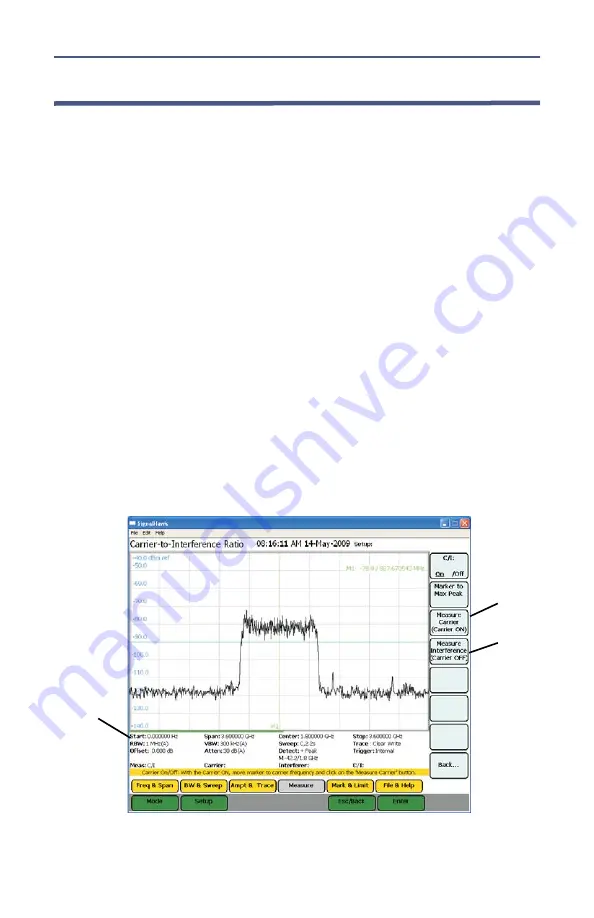
Carrier-to-Interference Ratio
Calculates the ratio of the carrier signal power to the power level of the noise
and interference signals.
To determine the ratio, two measurements need be done. First sweep should
be the carrier and interferer. The second sweep should be the interferer alone.
Note:
Because the transmitted carrier must be turned off for the
second portion of this measurement, access to the transmitter is
needed to complete this procedure.
1.
Do one of the following:
Move marker to the desired frequency.
Note:
The default marker placement assumes the carrier to be
measured is the center of the frequency span. It can be moved via
the arrow keys and/or wheel.
Select Marker to Max Peak to quickly identify the signal to be
measured.
2.
Measure the carrier signal.
3.
Turn off the transmitter.
4.
Measure the noise and interference signal levels as follows:
Note:
The carrier power and interferer power will be displayed in
selected power units, and the ratio in dB.
Figure
48
Example, Carrier-to-Interference Ratio - Carrier On
Measurement
Settings
STEP 2
STEP 3
Note:
In the status area, the carrier power, interferer power
will be displayed in selected power units, and the ratio in dB.
Summary of Contents for SignalHawk SH-36S-PC
Page 26: ...SignalHawk PC and Rack Mount Models 11 Figure 7 Select DSP Device List ...
Page 67: ...Measurements 52 Figure 41 Example Channel Power Integration Bandwidth STEP 2 STEP 3 ...
Page 116: ...SignalHawk PC and Rack Mount Models 101 Figure 75 Menu Map BW Sweep Menu All Measurements ...
Page 117: ...Menu Maps 102 Figure 76 Menu Map Amplitude All Measurements ...
Page 118: ...SignalHawk PC and Rack Mount Models 103 Figure 77 Menu Map Measurement All Measurements ...
Page 119: ...Menu Maps 104 Figure 78 Menu Map Mark Limit Menu All Measurements ...
Page 120: ...SignalHawk PC and Rack Mount Models 105 Figure 79 Menu Map File Help All Measurements ...
Page 121: ...Menu Maps 106 Setup Function Menu Maps Figure 80 Map Setup Mode Main Screen ...


