


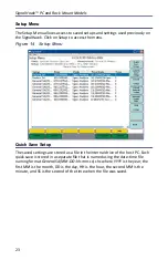


Settings
32
RBW goes from 100 Hz - 1 MHz, steps of 1 / 3 / 10 (e.g.: 1 kHz to 3 kHz to 10 kHz
to 30 kHz, etc.)
Video BW Mode (VBW) determines how much smoothing takes place.
Note:
VBW goes from 10 Hz to 300 kHz.
Wide (high) VBW setting:
Faster sweep times, but can obscure signal
details.
Narrow (lower) VBW setting:
Better trace smoothing for signals
present in high noise levels.
As the VBW is reduced, longer sweep times will be necessary to obtain a
measurement. To be useful, VBW must be narrower than RBW. No smoothing
takes place when VBW is greater than or equal to RBW.
Resolution & Video BW Modes
Click on these to toggle RBW or VBW, respectively, between automatic and
manual control. In automatic, they are controlled by the current span and the
values of Span/RBW and RBW/VBW. If either the RBW or VBW is changed, these
will switch to manual.
Auto RBW sets the RBW based upon the frequency span. When in Auto mode,
the RBW is set according to the nearest ratio of the Span/RBW selection. The
default ratio is 300. When the frequency span is reduced, the RBW will also be
reduced accordingly.
Example -
When the span is changed to 3600 MHz, the RBW will
automatically be set to 1 MHz. When the span is reduced to 100
MHz, the RBW will automatically reduce to 300 kHz.
Auto VBW sets the VBW based upon the RBW value. When in Auto mode, the
VBW is set according to the nearest ratio as set using the VBW/RBW selection.
The default ratio is 3. As the RBW span is reduced the VBW will be reduced
accordingly.
Example -
When the RBW is changed to 1MHz, the VBW will auto-
matically be set to 300kHz. When the RBW is reduced to 30kHz, the
VBW will automatically be set to 10kHz.
Summary of Contents for SignalHawk SH-36S-PC
Page 26: ...SignalHawk PC and Rack Mount Models 11 Figure 7 Select DSP Device List ...
Page 67: ...Measurements 52 Figure 41 Example Channel Power Integration Bandwidth STEP 2 STEP 3 ...
Page 116: ...SignalHawk PC and Rack Mount Models 101 Figure 75 Menu Map BW Sweep Menu All Measurements ...
Page 117: ...Menu Maps 102 Figure 76 Menu Map Amplitude All Measurements ...
Page 118: ...SignalHawk PC and Rack Mount Models 103 Figure 77 Menu Map Measurement All Measurements ...
Page 119: ...Menu Maps 104 Figure 78 Menu Map Mark Limit Menu All Measurements ...
Page 120: ...SignalHawk PC and Rack Mount Models 105 Figure 79 Menu Map File Help All Measurements ...
Page 121: ...Menu Maps 106 Setup Function Menu Maps Figure 80 Map Setup Mode Main Screen ...


