PIVOT™ 180
7
WWW.BIGASSFANS.COM ©2011 DELTA T CORP. ALL RIGHTS RESERVED
PIVOT™ 180
Electrical installation
•
The installation of a Big
Ass
Fan must be in accordance with the National Electrical Code, ANSI/NFPA 70-2011, and all local codes.
•
Acceptable Unshielded Cable Types: Stranded THHN / THNW, rated for 600V & 158°F-194°F (75°-90°C) in metallic conduit.
•
Acceptable Shielded Cable Types: RHH / RHW-2, rated for 600V & 158°F–194°F (75°–90°C); Belden 29501 through 29507; RHH/
RHW-2, tray rated for 600V & 158°F-94°F (75° to 90°C); Shawflex 2ACD / 3ACD or equivalent.
•
MC cable (stranded or solid core) cannot be used for fan output/motor input leads.
•
The motor leads from the fan control to the fan cannot be greater than 400 ft (121.9 m).
•
The fan must be visible from its controller unless a suitable means of disconnect is used at the motor.
•
The output/motor leads cannot share the same conduit or piping as the AC power supply. AC supply feeds for one fan controller may
share the same conduit with AC supply feeds for one or more controllers.
•
AC supply feeds for a fan controller and the output/motor leads for the same fan may not share a conduit.
•
AC supply feeds for one fan controller cannot share conduit with output/motor leads from one or more controllers/VFDs.
•
All unused conductors that share a conduit with the AC supply feeds must be grounded on both ends.
•
Controller output/motor input leads cannot share a conduit with any other controller’s output/motor leads.
•
Controller output/motor input leads cannot share a conduit with any other controller’s AC supply feed.
Before beginning installation, review the mechanical and electrical installation guidelines below.
Mechanical installation
•
Select a mounting location free from obstructions that may interfere with the fan’s movement.
•
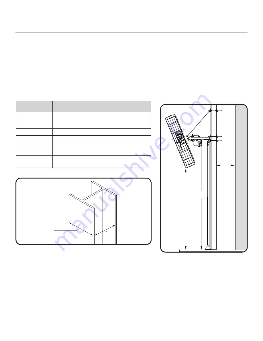
The underside of the Column Mount must be located at least 14 ft (4.27 m) from the ground so that the lowest point of the fan is at
least 11 ft (3.35 m) from the ground.
•
The column must be at least 4” (10.2 cm) away from walls.
•
The column width must be between 8” (20.3 cm) and 15” (38.1 cm).
•
The column depth must be no more than 15” (38.1 cm).
•
A scissor lift or other suitable means for lifting the weight of the fan and at least two (2) installation personnel will be required.
•
The fan installation area must be free of obstructions such as lights, cables, sprinklers, or other building structure. The airfoils should
have at least 2 ft (0.61 m) of clearance from any obstructions.
•
Adhere to the safety requirements in the table below when selecting the fan location.
Safety
requirement
Minimum distances
Clearance
≥2 ft from all fan parts. The fan installation area
must be free of obstructions such as lights, cables,
sprinklers, or other building structure.
Airfoil height
≥10 ft above the floor
HVAC equipment
≥1x fan diameter if at same level or above diffuser. ≥2x
fan diameter if below diffuser.
Fan spacing
2.5x fan diameter, center-to-center
Radiant/IR heaters See the manufacturer’s requirements for the minimum
clearance to combustibles.
Preparing the work site
Pre-Installation (cont.)
Distance Requirements
Width and Depth Requirements
Width Range:
8–15 in. (20.3–38.1 cm)
Max Depth:
15 in. (38.1 cm)
11 ft
(3.35 m)
14 ft
(4.27 m)
4 in
(10.2 cm)
W
all
Summary of Contents for Pivot 180
Page 1: ...INSTALLATION GUIDE For help call 1 877 BIG FANS or visit www bigassfans com Pivot 180...
Page 46: ......
Page 48: ......
Page 50: ......
Page 59: ......


