background image

8’ - 24’ POWERFOILPLUS™, POWERFOIL™, & WICKERBILL FANS

WWW.BIGASSFANS.COM     ©2010 DELTA T CORP.     DBA BIG ASS FAN     ALL RIGHTS RESERVED

12

WWW.BIGASSFANS.COM     ©2010 DELTA T CORP.     DBA BIG ASS FAN     ALL RIGHTS RESERVED

8’ - 24’ POWERFOILPLUS™, POWERFOIL™, & WICKERBILL FANS

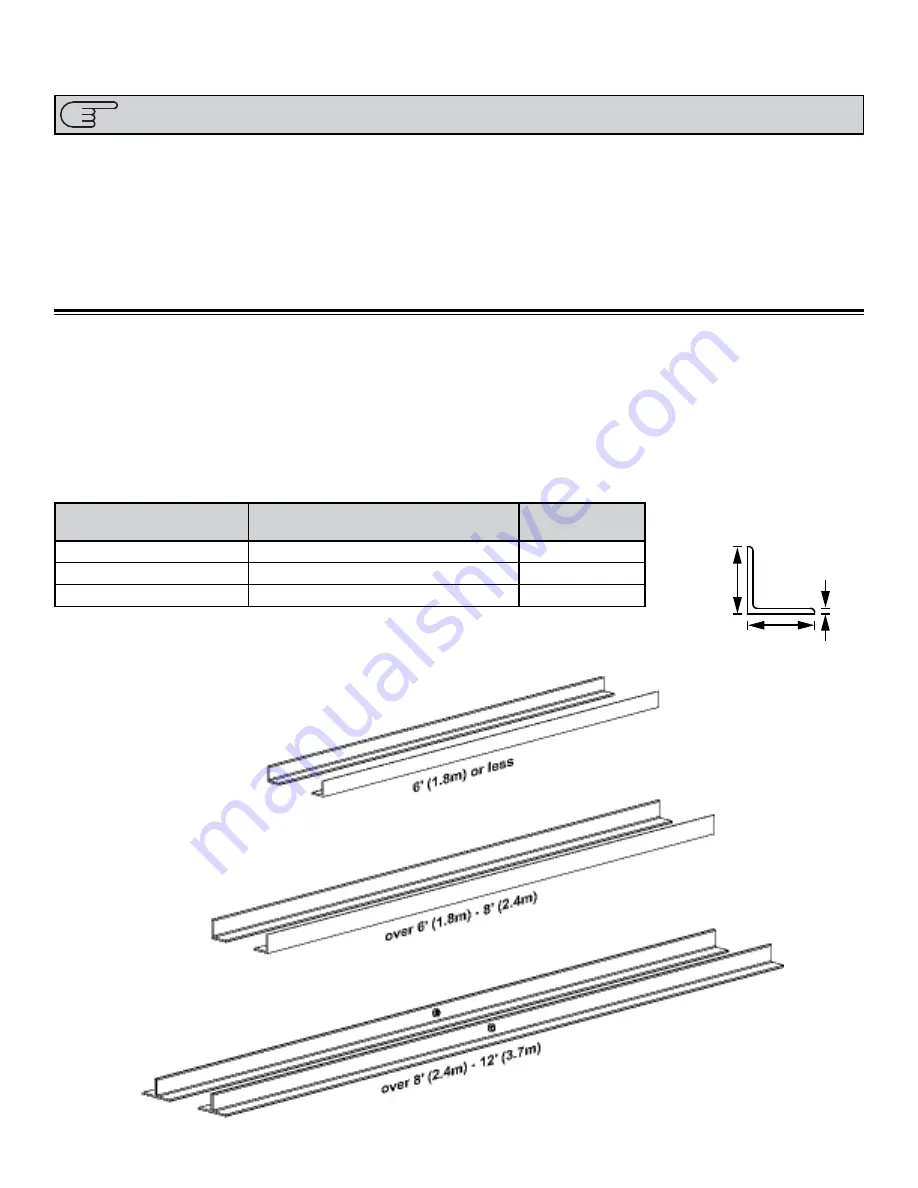
1. Select Proper Angle Irons

NOTE: Angle irons and angle iron hardware are not included with the fan.

CAUTION: Do not install the fan from a single purlin, truss, or bar joist. 

CAUTION: Unsupported angle iron spans should not exceed 12 ft (3.7 m).

Follow the table below when selecting angle irons for fan installation.

Height

Width

Ø 9/16” 

(1.4 cm)

Thickness: 

1/4” (6 mm)

Angle Iron Side View

(see table for dimensions)

Thickness

Angle Iron Span

(between mounting points)

Minimum Angle Iron Dimensions 

(W x H x T)

Number of Angle 

Irons Needed

6 ft (1.8 m) or less

2.5” (6.4 cm) x 2.5” (6.4 cm) x .25” (0.6 cm)

2

over 6 ft (1.8 m)-8 ft (2.4 m) 

3” (7.6 cm) x 3” (7.6 cm) x .25” (0.6 cm)

2

over 8 ft (2.4 m)-12 ft (3.7 m) 

3” (7.6 cm) x 3” (7.6 cm) x .25” (0.6 cm)

4*

*2 pairs of angle irons. Pairs should be placed back to back and fastened in center (see step 2).

Mounting Method 2: Angle Irons

If you are installing the fan to an I-beam and have attached the upper yoke (p. 11), proceed to “Hanging the Fan” 

(p. 18).

WARNING: The fan should not be installed unless the structure on which the fan is to be mounted is of sound construction, 

undamaged, and capable of supporting the loads of the fan and the method of attachment to the structure. A structural 

engineer should verify that the structure is adequate prior to fan installation. Verifying the stability of the mounting structure  

is the sole responsibility of the customer and/or end user, and Big Ass Fans hereby expressly disclaims any liability arising 

therefrom, or arising from the use of any materials or hardware other than those supplied by Big Ass Fans or otherwise 

specified in these installation instructions.

WARNING: Never use beam clamps when mounting the fan to angle irons! Beam clamps are only intended for I-beam 

installations.

Summary of Contents for 8' - 24' Powerfoil

Page 1: ......

Page 2: ...tween the fan and the HVAC equipment or other air moving equipment should be no less than 2x the fan s diameter when measured from the center of the fan to the equipment Will the distance between mult...

Page 3: ...of the following United States Patents 6 244 821 6 589 016 6 817 835 6 939 108 7 252 478 7 284 960 D607 988 D587 799 7 654 798 and other patents pending Installation Guide 301110 Nov 2010 The C UL US...

Page 4: ...NG To reduce the risk of fire electric shock and injury to persons Big Ass Fans must be installed with Big Ass Fan supplied controllers that are marked on their cartons to indicate the suitability wit...

Page 5: ...xtension Tube 20 4 Attach Motor Frame to Lower Yoke 20 Installing Guy Wires 1 Attach Eyebolt to Motor Frame 21 2 Attach Beam Clamp 21 3 Route Guy Wire Through Gripple 22 4 Install Three Remaining Guy...

Page 6: ...Controllers 56 Additional Input Power Considerations Input Voltage Irregularities 58 Delta Secondary 58 Branch Circuit Protection 59 KBDA Controller Specifications and Environmental Ratings 60 Allen...

Page 7: ...ndustrial setting More importantly you can rest assured that you have a product that is backed by extensive research thorough testing and quality manufacturing If you have any questions or comments co...

Page 8: ...5 RPM 208 230 460V 5 3 208V 5 0 230V 2 5 460V 63 RPM 147 569 cfm 69 645 L S 88 224 cm 239 lbs 108 kg 4 ft 0 91 m 18 ft 5 5 m 1 5 HP 1725 RPM 208 230 460V 5 3 208V 5 0 230V 2 5 460V 55 RPM 178 568 cfm...

Page 9: ...hed lines indicate internal boxes Drawings below are not to scale 2 Lower Yoke 2 Beam Clip 2 Spacer Upper Yoke 10 Winglet2 Extension Tube3 Safety Cable4 Main Box Controller5 Motor Hub 1 Airfoil retain...

Page 10: ...0 5 16 Flat Washer 20 5 16 18 Nylock Nut 4 Gripple Eyebolt Hardware1 1 Locking Carabiner 1 1 4 Beam Clip 1 1 4 20 x 1 Eyebolt 1 1 4 20 Hex Nut 1 Gripple 1 Guy Wire 2 Wire Rope Clip Parts Included NOTE...

Page 11: ...21 lbs 10 kg 12 ft Powerfoil foils 94 lbs 42 kg 6 ft Extension 25 lbs 11 kg 14 ft Wickerbill foils 91 lbs 41 kg 7 ft Extension 29 lbs 13 kg 14 ft Standard foils 91 lbs 41 kg 8 ft Extension 33 lbs 15...

Page 12: ...ture and allows the fan to adjust its center of gravity C Extension Tube Extends the fan from the ceiling D Lower Yoke Connects motor hub assembly to mounting assembly E Motor see p 2 for details F Ai...

Page 13: ...PLUS POWERFOIL WICKERBILL FANS Allen Bradley Controller Diagram Optional A VFD The Variable Frequency Drive VFD controls AC power to the motor B Fuses Protects the system from power surges and over cu...

Page 14: ...n If this flexing causes a clearance problem we suggest installing a stiffening strut to a nearby beam If the fan s extension tube is 4 ft 1 2 m or longer the fan s lateral movement must be secured us...

Page 15: ...ard The ceiling then turns the upward flow inward back toward the low pressure area above the fan where it is pulled back toward the floor This creates a convection like air current that gathers momen...

Page 16: ...ght where you need it most If you are using a PowerfoilPlus fan you will notice that it delivers air from a much higher angle overcoming many of the obstacles outlined below Make sure people are not h...

Page 17: ...ding structure 1 Attach Upper Yoke to I Beam Measure the flange width of the I beam from which the fan will be hung Consult the tables and diagram below to determine what size upper yoke is included w...

Page 18: ...ngle irons Pairs should be placed back to back and fastened in center see step 2 Mounting Method 2 Angle Irons If you are installing the fan to an I beam and have attached the upper yoke p 11 proceed...

Page 19: ...t lbf 54 2 N m using a 3 4 socket with torque wrench Repeat step for remaining two 2 angle irons Proceed to step 4b Grade 8 Hardware Customer supplied a 2 1 2 13 Bolt b 4 1 2 Washers c 2 1 2 Nut Side...

Page 20: ...bar joist CAUTION The angle irons must be fastened to the roof structure at each end Fasten the angle irons to the roof structure mounting points at each end with customer supplied Grade 8 hardware as...

Page 21: ...he angle irons to the roof structure mounting points at each end with customer supplied Grade 8 hardware as shown CAUTION The angle irons with fan mounting holes should be positioned on the inside fac...

Page 22: ...gle irons CAUTION The angle irons should be aligned with the outermost holes of the upper yoke Tighten the bolts to 98 ft lbf 133 N m using a 3 4 socket with torque wrench CAUTION After attaching the...

Page 23: ...t the diagram below for distances between the angle irons CAUTION The motor frame is heavy Use caution when raising it Tighten the bolts to 40 ft lbf 54 2 N m using a 3 4 socket with torque wrench CAU...

Page 24: ...er Yoke Fasten the extension tube to the upper yoke with the Single Pivot Hardware as shown Before tightening the bolts allow the extension tube to hang freely and balance itself Tighten the bolts to...

Page 25: ...around the I beam leaving as little slack as possible If possible the shackle should be on the topside of the I beam Securely tighten the shackle Proceed to step 3 Angle Iron Mount with Extension Tub...

Page 26: ...N m using a 3 4 socket with torque wrench Lower Yoke Hardware BAF Supplied a 2 1 2 13 x 5 GR 8 Bolt b 4 1 2 Flat Washer c 2 1 2 13 Nylock Nut b a c b 4 Attach Motor Frame to Lower Yoke Attach the moto...

Page 27: ...g Carabiner to Motor Frame Secure the locking carabiner to the motor frame as shown Gripple Eyebolt Hardware BAF Supplied a 4 Carabiners 2 Attach Beam Clamp Attach the beam clamp to an I beam or angle...

Page 28: ...The wires should be taut CAUTION Over tightening the guy wires could throw the fan off balance Once all of the guy wires are taut secure their loose ends with the wire rope clips as shown Wire Rope C...

Page 29: ...per oil vent cap is packaged in a bag attached to the motor unit If your fan model does not require an oil vent cap proceed to Installing Airfoils p 26 1 Replace Oil Plug CAUTION Do not remove oil plu...

Page 30: ...nt cap is packaged in a bag attached to the motor unit If your fan model does not require an oil vent cap proceed to Installing Airfoils p 26 1 Replace Oil Plug CAUTION Do not remove oil plug until fa...

Page 31: ...ached to the motor unit for these fans It is black and labeled OIL If your fan model does not require an oil vent cap proceed to Installing Airfoils p 26 1 Replace Allen Head Plug CAUTION Do not remov...

Page 32: ...rdware Kit BAF Supplied a 10 10 24 x 1 2 Bolt b 10 10 24 x 3 4 Barrel 2 Attach Airfoils to Hub WARNING Disconnect power to the fan before installing the airfoils Slide the airfoils onto the tabs of th...

Page 33: ...avoid a short circuit be very careful not to get metal chips in the control CAUTION The Big Ass Fans product warranty will not cover equipment damage or failure that is caused by improper installation...

Page 34: ...foilPlus 14 20 Powerfoil 14 20 Wickerbill MC 230 1 KB 1 1 5 2 1 5 200 250 1 20 A 230 5 6 A MC 230 3 KB 1 1 5 2 1 5 200 250 3 15 A 230 5 6 A MC 460 3 KB 1 1 5 2 1 5 400 480 3 10A 460 2 8 A MC 120 1 AB...

Page 35: ...n below If a controller with a rating other than NEMA Type 1 IP20 is required contact Big Ass Fans at 1 877 BIG FANS Allen Bradley KBDA 24D OL JOG REM FWD REV STOP LOC REM PGM Hz AC MOTOR SPEED CONTRO...

Page 36: ...t to or above a heat source or heat producing equipment For Allen Bradley controller ambient temperature shall be between 14 F 10 C and 104 F 40 C For KBDA controllers ambient temperature shall be bet...

Page 37: ...ss of 15 mils and should not have large variations in insulation concentricity Acceptable Shielded Types Note The drain conductor included with shielded cables must be connected to both the motor fram...

Page 38: ...ircuit protection and disconnecting devices Failure to do so may result in personal injury and or equipment damage Refer to Power Requirements p 28 for specific ampacities AC supply feeds for one fan...

Page 39: ...otal maximum motor lead length for all Big Ass Fan single fan controllers SHALL NOT EXCEED 400 ft 122 m MC Cable may not be used for controller output motor leads Do not use solid core wiring of any s...

Page 40: ...class for controller output motor leads Do not connect multiple motors on a common ground return Motors should each have a dedicated ground return back to the fan controller See Grounding on the follo...

Page 41: ...otor ground must be connected to a ground terminal on the VFD as shown in the Standard Grounding diagrams on pp 36 37 This aids in keeping high frequency electrical noise off of the building s ground...

Page 42: ...8 24 POWERFOILPLUS POWERFOIL WICKERBILL FANS WWW BIGASSFANS COM 2010 DELTA T CORP DBA BIG ASS FAN ALL RIGHTS RESERVED 36 Standard Grounding for Powerflex 4 Controller Optional...

Page 43: ...37 WWW BIGASSFANS COM 2010 DELTA T CORP DBA BIG ASS FAN ALL RIGHTS RESERVED 8 24 POWERFOILPLUS POWERFOIL WICKERBILL FANS Standard Grounding for Powerflex 4M Controller Optional...

Page 44: ...8 24 POWERFOILPLUS POWERFOIL WICKERBILL FANS WWW BIGASSFANS COM 2010 DELTA T CORP DBA BIG ASS FAN ALL RIGHTS RESERVED 38 Shielded Motor Cable Grounding for Powerflex 4 Controller Optional...

Page 45: ...39 WWW BIGASSFANS COM 2010 DELTA T CORP DBA BIG ASS FAN ALL RIGHTS RESERVED 8 24 POWERFOILPLUS POWERFOIL WICKERBILL FANS Shielded Motor Cable Grounding for Powerflex 4M Controller Optional...

Page 46: ...8 24 POWERFOILPLUS POWERFOIL WICKERBILL FANS WWW BIGASSFANS COM 2010 DELTA T CORP DBA BIG ASS FAN ALL RIGHTS RESERVED 40 Multi Fan Grounding for Powerflex 4 Controller Optional...

Page 47: ...41 WWW BIGASSFANS COM 2010 DELTA T CORP DBA BIG ASS FAN ALL RIGHTS RESERVED 8 24 POWERFOILPLUS POWERFOIL WICKERBILL FANS RFI EMI Grounding for Powerflex 4 Controller Optional...

Page 48: ...8 24 POWERFOILPLUS POWERFOIL WICKERBILL FANS WWW BIGASSFANS COM 2010 DELTA T CORP DBA BIG ASS FAN ALL RIGHTS RESERVED 42 RFI EMI Grounding for Powerflex 4M Controller Optional...

Page 49: ...ystem KBDA NEMA type 4X IP65 controllers do not provide this option and should only be installed on solidly grounded distribution systems Disconnecting MOVs To prevent controller damage the MOVs conne...

Page 50: ...cian should perform the installation This diagram is for a KBDA controller 200 250V using single phase input from AC power supply See the electrical diagram provided with the controller for detailed v...

Page 51: ...uld perform the installation This diagram is for a KBDA controller 200 250V 400 480V using three phase input from AC power supply See the electrical diagram provided with the controller for detailed v...

Page 52: ...can cause electric shock or damage to the motor and controller A qualified electrician should perform the installation This diagram is for an Allen Bradley Powerflex 4 Controller 100 125V using single...

Page 53: ...electric shock or damage to the motor and controller A qualified electrician should perform the installation This diagram is for an Allen Bradley Powerflex 4M Controller 200 250V using single phase in...

Page 54: ...use electric shock or damage to the motor and controller A qualified electrician should perform the installation This diagram is for an Allen Bradley Controller 200 250V 400 480V using three phase inp...

Page 55: ...use electric shock or damage to the motor and controller A qualified electrician should perform the installation This diagram is for an Allen Bradley Controller 575 600 V using three phase input from...

Page 56: ...S FAN ALL RIGHTS RESERVED 50 Wiring the Motor Bonfiglioli Motor 100 125 200 250 Volts CAUTION Install jumpers as shown Motor Leads from 100 125V 200 250V Fan Controller Wiring the Motor Bonfiglioli Mo...

Page 57: ...wire the motor as shown in Wiring the Motor Reliance Baldor Motor 200 250 Volts CAUTION Install jumpers as shown 400 480V System 5 200 250V System Wiring the Motor Reliance Baldor Motor 200 250 Volts...

Page 58: ...ed speed potentiometer is set to zero 0 3 The VFD s display LEDs should be lit at this point If the LEDs are not lit re verify proper AC supply voltage at disconnect terminals If necessary refer to Tr...

Page 59: ...the cable system is absorbing too much of the fan controller s output current again via high frequency cable charging Short Circuit The controller sees an electrical short circuit between motor phase...

Page 60: ...o change the display to read one of the following 1010 for motor lead lengths less than 100 ft 30 5 m 1011 for motor lead lengths greater than 75 ft 22 9 m 9 Press the READ ENTER button again to save...

Page 61: ...at the bottom of the controller s fuse block If necessary refer to Troubleshooting Allen Bradley Controllers p 68 4 With speed reference or door mounted speed potentiometer 1 set to minimum or zero tu...

Page 62: ...up procedures it is recommended that the installer perform this step and the following steps with the controller door open Turn the disconnect actuator 3 90 clockwise to energize the control panel Th...

Page 63: ...eration for 30 to 60 minutes in order to verify satisfactory operation If the fan system is going to suffer from any condition conducive of a fault it will happen during this time frame with the excep...

Page 64: ...stall Delta Wye Isolation Transformer with grounded secondary 1 1 turns ratio Ungrounded distribution system Supply transformer exceeds established kVA limit see table below Install Line Reactor More...

Page 65: ...fan controllers should be connected so that only phase A and phase C are utilized Each power lead should measure 120V to Ground Branch Circuit Protection CAUTION The KBDA NEMA type 4X IP65 fan control...

Page 66: ...Trip occurs at 427VDC bus voltage equivalent to 302VAC incoming line Under Voltage 100 120VAC Input Trip occurs at 215VDC bus voltage equivalent to 76VAC incoming line 200 240VAC Input Trip occurs at...

Page 67: ...C Input Trip occurs at 1005VDC bus volt age equivalent to 711VAC incoming line 100 120VAC Input Trip occurs at 210VDC bus volta ge equivalent to 75VAC incoming line 200 240VAC Input Trip occurs at 210...

Page 68: ...ages can exist at the motor terminals as high as 1800V p p For motors without terminal blocks the preferred method of terminating these motors is shown below Use of wire nuts should be avoided when po...

Page 69: ...to Ceiling Height ft Starting Fan Speed 40 4 40 6 Stand directly below the tips of the fan blades with hand outstretched If you feel a draft slightly turn down the fan speed 0 5 Repeat until the draf...

Page 70: ......

Page 71: ...he cable should be wrapped around the I beam angle irons leaving as little slack as possible The shackle should be securely tightened and located on the topside of the I beam angle irons 2 Ensure all...

Page 72: ...ecurely connected Make sure the Disconnect Switch and 3 Position Switch are in the ON position Verify that supply power is adequate and functional Contact Customer Service at 1 877 BIG FANS The Variab...

Page 73: ...Loss Detection Indicates that the drive has detected a loss of one of the phases in the 3 phase AC line input Keypad Communication Error Indicates that the keypad failed to initialize when the drive...

Page 74: ...Faults Automatically As previously mentioned Type 1 faults will clear themselves automatically however the most recent 3 will be stored in the VFD s fault buffer Refer to Powerflex Quick Start Guide...

Page 75: ...unstable frequency display on the VFD This would indicate a corrupted motor feedback due to a foreign signal presence Refer to the following section s Conduit and Piping Guidelines p 32 Wiring the Mo...

Page 76: ...eakdown The motor should be replaced at this time If the motor resistance is found to be OK this test should be repeated for the associated motor cabling Use of MC Cable and or any other solid core wi...

Page 77: ...ts as listed in the Machinery Directive 98 37 EC Low Voltage Electrical Equipment Directive 73 23 EEC and the EMC Directive 89 336 EEC Big Ass Fans systems that are fabricated to meet these requiremen...

Page 78: ...Ceiling Fan PP10 10 3 0 m Powerfoil Plus Industrial Ceiling Fan ST08 8 2 4 m Standard Industrial Ceiling Fan PP12 12 3 6 m Powerfoil Plus Industrial Ceiling Fan ST10 10 3 0 m Standard Industrial Ceil...

Page 79: ...of Big Ass Fans do not emit equivalent continuous sound pressure levels in excess of 65 dB A Electrical Installation Acceptable Cable Types CE installations require the use of shielded cabling only Al...

Page 80: ...und Rod Building Steel if present Building Steel if present Connection to Ground Grid or Building Steel via Fan Mounting Structure Shielded Cable With or Without Drain Lead Shielded Cable With or With...

Page 81: ...is required at all cable entry exit points Grounding must follow these recommendations to satisfy CE requirements Fan Controller Enclosure EMI RFI Filter Shielded Cable With or Without Drain Lead Inpu...

Page 82: ......

Page 83: ...installed more than 10 days after receipt by the customer the customer will be requested to provide satisfactory proof via documentation as to the actual date that the products were actually placed in...

Page 84: ...uct or the affected components as provided above Big Ass Fan Company reserves the right to make the final determination based on its own evaluation of the components as to whether 1 the problem in que...

Page 85: ...use you have waited too long to return the original component see Responsibility Agreement 3 When you receive the replacement part you have 10 working days to remove and replace the existing component...

Page 86: ...s outside the scope of the warranty or 2 the warranty period has expired If there is no warranty coverage we will send you a detailed letter of explanation We also will charge you for the replacement...

Page 87: ...tomer Service Department The RMA must appear on the outside of the box being returned Items without an RMA will not be accepted Date Replacement Parts Should Be Shipped if known Please do not request...

Page 88: ...nd all replacements and such invoice will be paid within 15 days of receipt of the same The undersigned agrees to ship to Big Ass Fan Company s location at 2425 Merchant Street Lexington KY 40511 all...

Page 89: ...Fan Model Fan Model Fan Model Serial Serial Serial Location Location Location Date Initials Date Initials Date Initials Annual Maintenance Checklist...

Page 90: ......

Page 91: ...to be avoided they are also brought to the supervisor s attention and instructed how to bypass the area if required Safety Rules and Regulations listed The facility manager understands all electrical...

Page 92: ...discussed at check in If extension tube is 4 ft 1 2 m or longer guy wires are in place and there is no evidence of a wobble Supervisor has supplied and explained the Installation Guide If not explain...

Page 93: ......

Page 94: ......

Page 95: ......

Page 96: ...310310 2425 Merchant Street Lexington KY 40511 1 877 BIG FANS 1001040101...

Reviews: