Installation, Operation and Maintenance Manual
VCIOM-15345-EN Rev. 1
February 2022
59
Customizing Biffi EHO
Section 8: Customizing Biffi EHO
Menu Name
Menu
Key
Configuration/
Calibration Value
Default
Action
RELAY4 SETTING
Configure Relay4 to provide either a
continuous or flashing signal if Relay4
Function is met. Flashing will be in
1 s intervals.
S4
0 = Continuous
1 = Flashing
0 = Continuous
RELAY5 FUNCTION
Set Biffi EHO's configurable relays to
provide various actuator status indication.
r5
0 = Generic (Host Control)
1 = Monitor Alarms
2 = Unit Alarms
1 = Monitor Alarms
RELAY5 SETTING
Configure Relay5 to provide either a
continuous or flashing signal if Relay5
Function is met. Flashing will be in
1 s intervals.
S5
0 = Continuous
1 = Flashing
0 = Continuous
NETWORK SETUP
Set communication protocol configurations
for the Biffi EHO.
nS
Yes/No
N/A
NETWORK NODE ADDRESS/SLAVE ADDRESS
Set the node address/slave address for
the Biffi EHO. A unique node address/slave
address must be assigned for each
Biffi EHO in a multi-actuator network.
Si
1 - 253
1
BAUD RATE
Set the baud rate for the Biffi EHO.
Note: Baud rate can be changed for
Modbus network adapters only for
NETWORK ADAPTER options for
1 (MODBUS E>NET), 2 (MODBUS BUS),
3 (MODBUS TCP/IP). All other
communication protocols will be
factory set and cannot be changed.
br
0 = 4800
1 = 9600
2 = 19200
3 = 38400
4 = 57600
5 = 115200
2 = 19200
PARITY
Set the parity for the communication
port in the Biffi EHO.
Pn
0 = Even
1 = Odd
2 = None
0 = Even
Menu Name
Menu
Key
Configuration/
Calibration Value
Default
Action
NETWORK ADAPTER
Set the communication
protocol for the Biffi EHO.
Note: This is factory set.
nA
0 = No Network Adapter Installed
1 = MODBUS E>NET
2 = MODBUS BUS
3 = MODBUS TCP/IP
4 = CONTROLINC
5 = DEVICENET
6 = FOUNDATION FIELDBUS BLOCK MODE
7 = FOUNDATION FIELDBUS MODULATION MODE
8 = PROFIBUS
9 = HART BLOCK MODE
10 = HART MODULATION MODE
Feedback
Only
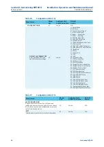
Table 20.
Configuration Table (8)
Table 21.
Configuration Table (9)


