


- 7 -
DIAGRAMS
3
diaGrams
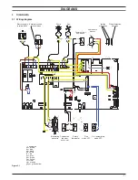
3 .1 wiring diagram
figure 3 .1
1
2
3
L
N
gnye bu
bn
bn
bk
bu
bn
bu
bn
bk bu
gnye
bn bu
bn
bu
M
~
bu bn gnye
t
wh
wh
t
bu
bu
bk
bk
Ignition
electrodes
Flame detection
electrode
External controls
terminal block
Electric supply
terminal block
Pump
M
~
Primary circuit
flow switch
Air pressure
sensor
C.h. temperature
probe NTC
Modulating
gas valve
Flue
probe NTC
ye
gy
bn = brown
bu = blue
bk = black
wh = white
rd = red
gy = grey
gn = green
ye = yellow
vt = violet
og = orange
gnye = green/yellow
bu
bn
gnye
bu
bk
bu bu
bn
bu
bk
wh
wh
rd
rd
P
rd
ye
gy
rd
gy
ye
gy
gy
bk
bk
ye
gy
1
2
3
1
3
4
bu
* = alternative
gnye
bk
bk
Safety
thermostat
bk
Combustion
chamber
over heat
bk bk
bk
bk
Fan