


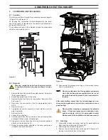


- 17 -
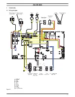
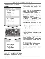
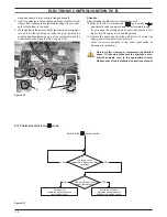
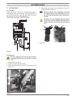
ElEctronic control/ignition p.c.b.
figure 8 .2
1
2
3
4
5
6
7
8
9
10
11
12
13
14
1
x1 connector
2
x6 connector
3
x7 connector
4
x4 connector
5
x2 connector
6
x15 connector
7
x11 connector
8
Lock-out signal lamp
9
Boiler reset button
10
Function control / C.h. temperature adjustment
11
Service knob
12
Appliance operation lights
13
x8 connector
14
Fuse 3,15 A F
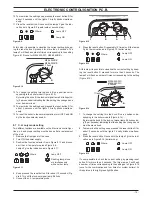
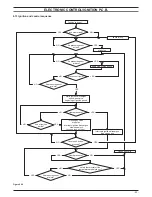
8 .3 checking the temperature
The temperature of the water is converted into an electric signal
by means of temperature probes.
The user, setting the desired temperature with the control panel
knobs operates the variable elements (10 Figure 8.2) of the elec-
tronic control p.c.b.
I
f the power requested is lower than 40% of the maximum power
output then control is achieved by switching ON the burner at
minimum power, then switching OFF (ON/OFF function). If the
power requested is higher, then the burner is switched ON at
maximum power and will control by modulating to 40% of the
maximum power output.
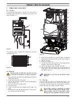
During the c.h. operation (Figure 8.3), the signal coming from the
c.h. temperature probe is compared to the signal given by the
control panel through the adjustment made by the user (knob
). The result of such a comparison operates the modulation
of the gas valve, consequently changing the useful output of the
boiler.
figure 8 .3
The control sequences in
function are illustrated in detail in
sections 8.2 and 8.3.
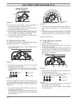
8 .4 Operation lights
The Electronic control/ignition p.c.b. is provided with three lamps
(L.E.D. indicators) 12 in Figure 8.2 that give optical information
during the operation of the boiler.
The green lamp on the left gives information whether the boiler
is in stand-by mode or during the normal operation of the boiler.
The following table gives the relationship between the lamp indi-
cation and its meaning.
A short pulse every 4 seconds
1 second ON 1second OFF
Boiler in stand-by condition.
(function control in
position).
Anti- freeze system active.
A short pulse every 4 seconds
1 second ON 1second OFF
Boiler ON condition
(function control in
or
position)
With the boiler switched ON (
) all the lamps (12 in Figure 8.2)
are activated.
The following table gives the relationship between each of the
possible lamp combinations and their meaning.