


- 34 -
Flue temperature probe NtC
17 flue temperature prObe ntc
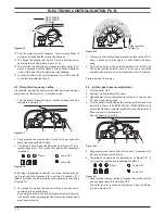
17 .1 function
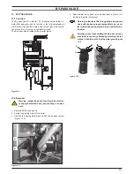
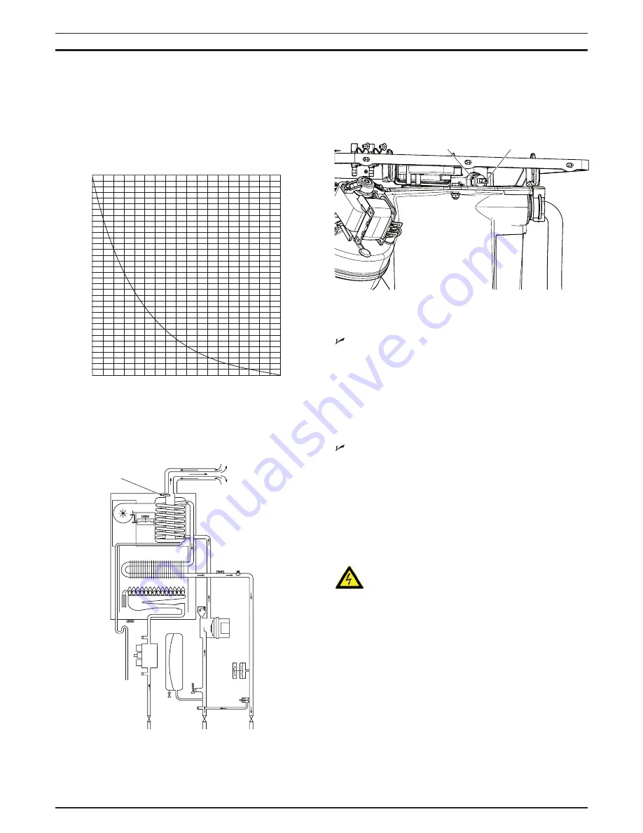
The Flue temperature probe NTC A in Figure 17.2 and Figure
17.3 senses the temperature of the combustion products that
flow through the condensing heat exchanger.
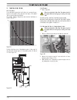
The relation between temperature and electrical resistance is
stated in Figure 17.1.
figure 17 .1
1000
1500
2000
2500
3000
3500
4000
4500
5000
5500
6000
6500
7000
7500
8000
8500
9000
9500
10000
10500
11000
11500
12000
12500
13000
13500
14000
14500
15000
15500
16000
16500
17000
17500
18000
18500
10 15 20 25 30 35 40 45 50 55 60 65 70 75 80 85 90 95 100
Ω
°C
If the temperature of the combustion products circuit reaches the
limit temperature, the Flue temperature probe NTC reduces the
gas flow rate to the burner. The temperature of the combustion
products should decrease to a safe value temperature.
figure 17 .2
a
In the case that the temperature of the combustion products
reaches a potentially dangerous value, it stops the boiler opera-
tion. It is therefore allowed the use of plastic materials for the flue
outlet pipes and bends.
the use of kits different from the original isn’t however al-
lowed, since the flue pipes are integral parts of the boiler.
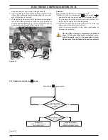
If not, the electronic control p.c.b. attempts to light the burner
and, at the end, locks the boiler and lights the lock-out signal
lamp.
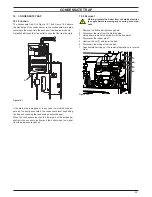
figure 17 .3
a
b
17 .2 checks
Overheat temperature value
1 Set the temperature control knobs to their max. position and
run the boiler in d.h.w. and c.h.
2 Allow the boiler to reach its maximum operating temperature
(monitor the temperature gauge on the instrument panel).
The boiler should maintain a temperature below that of the
Flue temperature probe NTC and no overheat intervention
should occur.
Temperature-resistance relationship.
1 Remove the probe (see section "Removal" page 34) to have
it at room temperature.
2 The electric resistance of the Flue temperature probe NTC at
room temperature of 20°C must be of approximately 12000 Ω
3 For other temperatures of the probe check the electrical re-
sistance according to the graph (Figure 17.1)
17 .3 removal
warning: isolate the boiler from the mains electrici-
ty supply before removing any covering or compo-
nent .
1 Remove all the case panels and the sealed chamber lid.
2 Disconnect the wires B from the Flue temperature probe NTC
(Figure 17.3).
3 Unscrew and remove the thermostat probe A (Figure 17.3)
from the condensing heat exchanger.
4 Assemble the Flue temperature probe NTC carrying out the
removal operations in reverse sequence.