


- 14 -
PUMP
7
pump
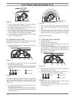
7 .1 function
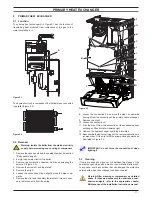
The pump A in Figure 7.1 and Figure 7.3 has the function of
making the water in the main circuit circulate through the main
heat exchanger, the condensing heat exchanger and therefore
through the c.h. system (during the c.h. function) or through the
secondary heat exchanger (during the d.h.w. function).
figure 7 .1
a
7 .2 checks
warning: isolate the boiler from the mains electrici-
ty supply before removing any covering or compo-
nent .
Check that the pump is not seized and that the movement of
the rotor is not subject to mechanical impediments.
With the boiler off, remove the front panel. Remove the air re-
lease plug of the pump and turn the rotor with a screwdriver.
Check the electrical continuity.
With the boiler off, remove the front panel and disconnect the
connector B (Figure 7.3).
Measure the electrical resistance between the pump supply con-
nections.
Electrical resistance of the windings (at ambient temperature)
must be about 213 Ω (coil 1) and 480 Ω (coil 2) (
Figure 7.2).
Check the absence of starting defects.
With the boiler off remove the front case panel.
Remove the air release plug from the pump. Start the boiler and
with a screwdriver, turn the rotor in the direction of the arrow.
If there is a defect in starting, the rotor will begin to turn normally
only starting it manually.
Check that the impeller is integral with the rotor.
With the boiler off remove the front and right hand side case pan-
els, lower the control panel and empty the primary circuit.
Remove the pump head by undoing the screws which hold it to
the pump body and check that the impeller is firmly joined to the
rotor.
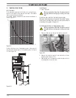
figure 7 .2
213 Ω
480 Ω
Coil 1
Coil 2
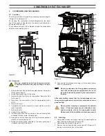
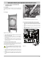
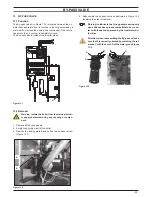
7 .3 removal pump
warning: isolate the boiler from the mains electrici-
ty supply before removing any covering or compo-
nent .
1 Remove the case panels and the sealed chamber lid (section
"Body panels" page 5).
2 Empty the primary circuit of the boiler.
3 Disconnect the connector B (Figure 7.3) following the indica-
tions given on the connector box.
4 Disconnect the earth connector T (Figure 7.3).
5 Loosen the connection D (Figure 7.3),and pull up and turn to
the left the pipe E.
6 Remove the fork H, loosen the connection I and remove the
pipe L (Figure 7.3).
7 Remove the locking plate F (Figure 7.3).