


- 31 -
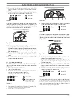
Fan and air pressure sensor
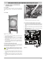
14 .3 removal of the fan
warning: isolate the boiler from the mains electrici-
ty supply before removing any covering or compo-
nent .
1 Remove all the case panels and the sealed chamber lid.
2 Disconnect the connectors C and the earth connection D
(Figure 14.4).
3 Disconnect the pipe E by the pressure test point F (Figure
14.4 Figure 14.4).
4 Unscrew the screw G and remove the bracket H (Figure
14.4).
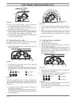
figure 14 .4
G
h
a
c
d
e
f
J
i
5 Remove the Fan by sliding it towards left (se the arrow in
Figure 14.4).
6 Assemble the fan carrying out the removal operations in re-
verse sequence.
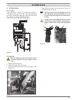
warning: re-assembling the fan ensure that the
hooks around the inlet port of the fan hung correct-
ly on the flue hood.
warning: after cleaning or replacement as detailed
above, if it deemed necessary to undertake a com-
bustion analysis, refer to the appropriate chapter
maintenance of the installation instructions manual .
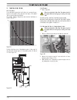
14 .4 removal of the air pressure sensor
warning: isolate the boiler from the mains electrici-
ty supply before removing any covering or compo-
nent .
1 Remove all the case panels and the sealed chamber lid.
2 Disconnect the wires I from the Air pressure sensor.
3 Remove the pipe J from the Air pressure sensor.
4 Unscrew the screws which hold the Air pressure sensor to the
frame.
5 Assemble the Air pressure sensor carrying out the removal
operations in reverse sequence.
warning: to correctly connect the air pressure sen-
sor, refer to figure 14 .5 .
figure 14 .5
J
pressure point p2
warning: after cleaning or replacement as detailed
above, if it deemed necessary to undertake a com-
bustion analysis, refer to the appropriate chapter
maintenance of the installation instructions manual .