


- 15 -
PUMP
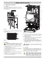
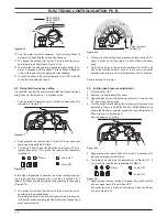
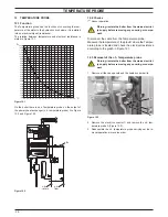
figure 7 .3
e
d
t
a
b
G
f
h
i
l
8 Unscrew the two screws G that hold the pump on the frame
and remove the pump.
Reassemble the pump carrying out the removal operations in the
reverse order. When reassembling the pump, check the correct
location of the O-ring gasket in the inlet port of the pump that
seals the connection between the pump and the return water
group.
7 .4 removal electrical capacitor
warning: isolate the boiler from the mains electricity
supply before removing any covering or component .
1 Remove the front and right hand side case panels.
2 Disconnect the connector B (Figure 7.3) following the indica-
tions given on the connector box.
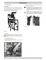
3 Remove the connector M of the cover box by levering with a
screwdriver in as shown in (Figure 7.4).
figure 7 .4
m
4 Remove the capacitor connection block N freeing it from the
hook O and pulling it as indicated by the arrow (Fig. 7.6).
figure 7 .5
n
O