


- 24 -
Modulating gas valve
9
mOdulatinG Gas valve
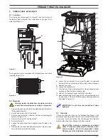
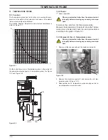
9 .1 function
The Modulating gas valve A in Figure 9.1
controls the gas inflow
to the boiler burner.
figure 9 .1
a
By means of an electric command given to the on-off operators
the passage of the gas through the Modulating gas valve can be
opened or closed.
By means of an electric command given to the modulation opera-
tor the pressure can be varied and therefore the gas flow rate to
the burner (modulation). The modulation operator has mechani-
cal components which allow the adjustment of the minimum and
maximum pressure exiting the valve.
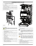
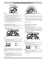
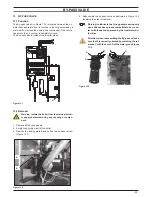
9 .2 nomenclature of the parts
- (figure 9 .2)
1
Minimum gas pressure adjustment
2
Maximum gas pressure adjustment
3
Modulation operator’s electric connectors
4
On-off operators electric connector
5
On-off operators
6
Gas valve inlet pressure test point
7
Gas valve outlet pressure test point
8
Modulation operator
figure 9 .2
7
8
6
4
5
1
2
3
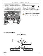
9 .3 adjustment
for the pressure values refer to the technical data section
of the user manual and installation instructions .
warning: isolate the boiler from the mains electrici-
ty supply before removing any covering or compo-
nent .
1 Remove the case panels and the sealed chamber lid (section
"Body panels" page 5).
2 Open the gas valve inlet pressure test point (6 in Figure 9.2)
at the valve input, connect a suitable pressure gauge and
check the gas pressure of the supply network.
3 Remove the gauge and close the pressure test point 6.
4 Open the gas valve outlet pressure test point (7 in Figure 9.2)
and connect the gauge;
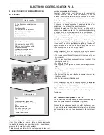
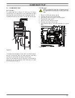
figure 9 .3
b
c
5 Remove the protection cap B (Figure 9.3) from the mechani-
cal pressure adjustment components levering with a flat
screwdriver in the slots C.
6 Start the boiler at its maximum power.
7 Rotate the maximum gas pressure adjustment (2 in Figure
9.2) until you obtain the required pressure (by rotating clock-
wise the pressure increases).
8 Turn the boiler off and disconnect one of the two connectors
(3 in Figure 9.2).
9 Start the boiler and rotate the minimum gas pressure adjust-
ment (1 in Figure 9.2) until you obtain the required pressure