


- 10 -
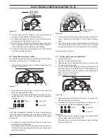
FAult Finding
7
C
omp
on
en
ts
to
ch
ec
k
S
ec
tio
n
of
the
m
anual
!
(n
ot
e
ref
.i
n
brac
ket
s)
---
---
--- (8)
--- (7)
17
.1
16
.2
15
.2
14
.2
13
12
.2
10
.2
9.4
8.10
7.2
--- (4)
18
.1
--- (3)
--- (2)
--- (1)
Loc
k---
out
sig
nal
lam
pre
d
Pres
sur
eg
aug
e
Saf
ety
val
ve
Exp
ans
ion
vesse
l
Inje
ctor
s
Flue
prob
eN
TC
Saf
ety
the
rm
ost
at
Det
ect
ion
ele
ctro
de
Ign
itio
nel
ectrod
e
Air
pre
ssure
senso
r
Fan
By---
pas
sv
alv
e
Main
circu
itte
mp.p
rob
e
Main
circu
itf
low
switch
Gas
val
ve(m
odul
atin
go
perat
or)
Gas
val
ve(o
n---
off
ope
rators
)
Boil
erse
ttings
Ele
ctro
nic
p.c.
b.
Fus
es(E
lec
tro
nic
p.c
.b.)
Pump
C.h
.cir
cuit
Conde
nsat
edr
ain
pip
ea
ndtr
ap
Flue
pipe
s
Gas
sup
ply
line
Pow
ers
upp
lyli
ne
De
fe
ct
#
O
n
c/
h
m
od
e
th
e
te
m
pe
ra
tu
re
of
th
e
ma
in
cir
cu
it
re
ach
es
75
C
an
d
th
e
c/h
sy
st
em
do
es
no
th
eat
.
J
In
co
rr
ec
tm
od
ul
at
io
n
J
J
J
N
oisy
bolie
r
J
J
OFF
Th
e
bo
ile
ro
pe
rat
es
co
rrec
tly
bu
tt
he
gas
pr
es
su
re
to
th
e
bur
ne
rr
em
ai
ns
at
m
in
im
um
.
J
J
---
W
at
er
le
ak
s
fro
m
th
e
saf
et
y
val
ve
du
r-
in
g
op
er
ation
on
c/
h
J
J
J
J
---
W
at
er
le
ak
s
fro
m
th
e
saf
et
y
val
ve
w
he
n
th
e
bo
ile
ris
of
f.
J
J
J
N
ote
U
se
fu
lin
fo
rm
at
io
n
ca
n
be
ob
ta
in
ed
al
so
fr
om
the
op
tic
al
in
dic
at
io
n
give
n
by
the
ap
pl
ia
nc
e
op
er
-
at
io
n
lig
hts
(s
ee
se
ctio
n
8.
4)
.
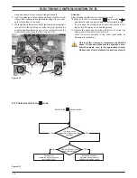
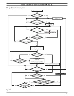
1
C
he
ck
fo
r230V~
between
lin
e
(L
)a
nd
ne
ut
ra
l(N
)
Ve
rif
y
th
e
in
te
gr
ity
of
su
pp
ly
ca
bl
e,
pl
ug
an
d
ex
te
rn
al
fu
se
s.
C
he
ck
the
po
la
rit
y
of
line
and
ne
ut
ral
co
nne
ct
io
n
2
Ve
rif
y
th
e
tig
htn
es
s
of
th
e
ga
s
su
pp
ly
pip
e,
th
e
position
of
st
op
val
ve
s.
C
he
ck
the
gas
pr
es
su
re
at
th
e
inl
et
te
st
po
in
to
ft
he
gas
val
ve
(s
ee
se
ct.
9.
3)
w
ith
th
e
bo
ile
ra
tr
est
an
d
du
rin
g
op
er
ation
an
d
co
mp
ar
e
it
w
ith
th
e
va
lu
es
gi
ve
n
on
th
e
in
st
alla
tio
n
bo
ok
le
t.
3
C
he
ck
fo
rs
ou
nd
ne
ss
an
d
ab
se
nc
e
of
ob
st
ru
ct
io
ns
.V
er
ify
th
at
th
e
flu
e
te
rmin
al
is
co
rr
ect
ly
in
st
alle
d
(se
e
cle
ar
an
ce
s)
an
d
en
-
su
re
th
at
exhaus
tg
as
is
no
ts
uc
ke
d
bac
k
by
the
bo
ile
r.
4
C
he
ck
fo
rs
ou
nd
ne
ss
of
th
e
ci
rc
ui
ta
nd
ve
rify
its
co
rr
ec
tf
ill
in
g
(s
ee
al
so
in
st
alla
tio
n
ma
nu
al)
.
5
A
ja
m
m
ed
by
---
pa
ss
co
ul
d
ca
us
e
th
e
ov
er
---
he
at
in
g
of
th
e
m
ai
n
ci
rc
ui
ta
nd
th
e
in
te
rv
en
tio
n
of
th
e
sa
fe
ty
th
er
m
os
ta
t.
6
C
he
ck
the
min
imu
m
ga
s
pre
ss
ure
at
th
e
ou
tle
tt
es
tp
oi
nt
of
th
e
ga
s
va
lv
e
(s
ee
se
ct.
9.
3)
an
d
comp
ar
e
it
w
ith
th
e
va
lu
e
giv
en
on
th
e
in
sta
lla
tion
book
le
t.
7
Ve
rif
y
th
e
cl
ea
nn
es
s
of
in
je
ct
or
s.
8
C
he
ck
th
e
pr
essu
riz
atio
n
of
th
e
ex
pa
nsio
n
ve
sse
l.
R
ef
er
to
th
e
in
st
al
la
tion
ma
nu
al
for
pr
op
er
va
lu
es
.