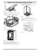
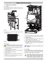
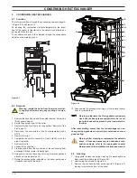
Biasi Riva Plus HE M296.24SR/C Service Manual Download Page 20

- 20 -

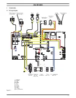
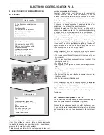
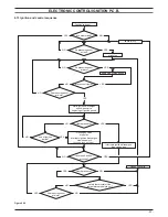
ElEctronic control/ignition p.c.b.

figure 8 .16

1 flash

M296.24SR/C

M296.28SR/C

4 flashes

b

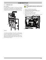
10 Turn the water control to minimum. Lock-out lamp blinks (2 

per second) indicating the setting has changed

11  To change the setting turn the knob B on a position corre-

sponding to the boiler model (Figure 8.16).

12  To memorize the setting keep pressed the reset button D for 

about 5 seconds until the lights F

  briefly  blinks  simultane

-

ously. At this point only the right green light flashes.

13  To reset the boiler to the normal operation turn it OFF and ON 

by the function selector knob A.

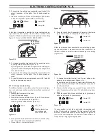
8 .8  reignition frequency setting

It is possible to select the minimum time that must pass between 
two ignitions of the burner in c.h. function mode.

1  Turn the boiler ON positioning the function selector knob A as 

indicated in Figure 8.17.

figure 8 .17

f

b

a

d

e

2  Keep pressed the reset button D for about 10 seconds until 

the lock-out signal lamp E blinks.

3  The lamps F should give the indication as in Figure 8.18 (re-

ignition frequency). If not, press the reset button repeatedly 
to obtain it.

figure 8 .18

Where:

Lamp OFF

Lamp ON

At this step it is possible to visualize the current setting by keep-
ing the reset button D pressed for more than 5 seconds. The 
lamps F

 will flash a number of times corresponding to the setting 

(Figure 8.19).

4  To change the setting turn the knob B on a position corre-

sponding to the desired delay.


By turning the knob B, the lock-out signal lamp E blinks quick-
ly (2 per seconds) indicating that the setting has changed and 
must be memorised.

figure 8 .19

Setting No.

Delay (minutes)

1

4

2

3

5

6

7

0

1 1/2

3

4

5 1/2

7

8 1/2

b

5  To memorize the setting keep pressed the reset button D for 

about 5 seconds until the lights F

  briefly  blinks  simultane

-

ously.

6  To reset the boiler to the normal operation turn it OFF and 

ON by the function selector knob A. In any case, the boiler 
automatically resets to its normal operation after 10 minutes.

Factory setting = 3 minutes

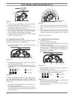
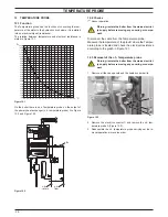
8 .9  ignition gas pressure adjustment

1  Turn the boiler OFF.
2  Remove the front panel of the case.
3  Open the gas valve outlet pressure test point (7, see section 

9.2) and connect the gauge.

4  Turn the boiler ON positioning the function selector knob A as 

indicated in Figure 8.20 (M296.24SR/C, M296.28SR/C) and 
ensure that the timer selector switch and room thermostat, if 

fitted, are set to “heat demand”.

  Run the boiler in c.h. mode.

figure 8 .20

f

b

a

d

e

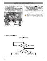
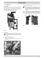
5  Keep pressed the reset button D for about 10 seconds until 

the lock-out signal lamp E blinks.

6  The lamps F should give the indication as in Figure 8.21. If 

not, press the reset button repeatedly to obtain it.

figure 8 .21

Where:

Lamp OFF

Lamp ON

7  Keep pressed the reset button D for about 5 seconds until the 

lock-out signal lamp E is switched OFF.

  The boiler runs in c.h. mode and the lamps F give the indica-

tion as in Figure 8.22.

Summary of Contents for Riva Plus HE M296.24SR/C

Page 1: ...System boiler Leave this manual adjacent to the gas meter Warning Service repairs must be carried out only by a qualified Gas Safety Registered Engineer who will be responsible for the current Regulat...

Page 2: ......

Page 3: ...electronic control p c b 21 8 12 Thermal control in the mode 22 8 13 Ignition and control sequence 23 9 Modulating gas valve 24 9 1 Function 24 9 2 Nomenclature of the parts 24 9 3 Adjustment 24 9 4 C...

Page 4: ...chamber Automatic air release valve Pump Detection electrode Combustion chamber over heat Condensing heat exchanger Flue temperature probe NTC C H temp probe Primary circuit pressure switch Condensate...

Page 5: ...ve screws A Figure 2 2 lift the panel and remove it Figure 2 2 A To remove the side panels loosen the screws B and C Figure 2 3 bring the base of the panels away from the boiler and lift them freeing...

Page 6: ...parts contained in the sealed chamber it is necessary to remove the lid of the sealed chamber For this purpose remove the front and side panels of the case remove the screws G as indicated in Figure 2...

Page 7: ...supply terminal block Pump M Primary circuit flow switch Air pressure sensor C h temperature probe NTC Modulating gas valve Flue probe NTC ye gy bn brown bu blue bk black wh white rd red gy grey gn gr...

Page 8: ...Circuit voltages Figure 3 2 Electrical voltages with burner on during c h or d h w operation Supply network 230 230 Pump 230 Modulating Gas valve Safety thermostat 0 Fan 230 12 V DC Air sensor pressu...

Page 9: ...sion vessel Safety valve Pressure gauge By pressing the reset push button the boiler turns on and operates cor rectly J J 6 J J J By pressing the reset push button the boiler starts the ignition cycle...

Page 10: ...ained also from the optical indication given by the appliance oper ation lights see section 8 4 1 Check for 230V between line L and neutral N Verify the integrity of supply cable plug and external fus...

Page 11: ...t from the wiring Figure 5 3 F H N P J I K M E O G C B C D L 8 Loosen the connection K and move the pipe L downwards freeing it from the connection of the primary heat exchanger 9 Remove the clip M 10...

Page 12: ...the pipe K from the connection of the condensing heat exchanger lift and rotate it towards right 10 Using pliers remove the spring L moving it to wards right and disconnect the rubber pipe M 11 Rotat...

Page 13: ...N O L M 4 Reassemble the exchanger carrying out the removal opera tions in reverse order Warning to lubricate the O ring gaskets exclusively use a silicone base grease compatible to be in con tact wi...

Page 14: ...tarting defects With the boiler off remove the front case panel Remove the air release plug from the pump Start the boiler and with a screwdriver turn the rotor in the direction of the arrow If there...

Page 15: ...the return water group 7 4 Removal electrical capacitor Warning isolate the boiler from the mains electricity supply before removing any covering or component 1 Remove the front and right hand side ca...

Page 16: ...e signal coming from the air pressure sensor The Electronic control ignition p c b has a safety function and any incorrect interventions or tampering can result in conditions of dangerous functioning...

Page 17: ...signal coming from the c h temperature probe is compared to the signal given by the control panel through the adjustment made by the user knob The result of such a comparison operates the modulation o...

Page 18: ...Useful output setting To set the useful output proceed as follows 1 Remove the front panel of the case 2 Take off the lid of the sealed chamber 3 Switch on the appliance at the mains isolating spur 4...

Page 19: ...iscon nect the c h temperature probe Figure 8 6 Lamps F give the indication as in Figure 8 11 Figure 8 11 Where Lamp OFF Flashing lamp alone or simultaneously with an other lamp 4 Keep pressed the res...

Page 20: ...change the setting turn the knob B on a position corre sponding to the desired delay By turning the knob B the lock out signal lamp E blinks quick ly 2 per seconds indicating that the setting has cha...

Page 21: ...fied the reason for failure Lock sequence Start the boiler until the burner is ignited With the burner firing interrupt the gas supply The Electronic control ignition p c b must carry out three comple...

Page 22: ...m room thermostat Starts the circulator Operates motorised valve Supplies the ignition device NO Circulator off Operates motorised valve Ignition device off YES YES Figure 8 27 Attention After install...

Page 23: ...pens gas valve beginning of ignition period flame presence end of ignition period NO NO YES closes gas valve stops fan interrupts ignition discharges memorizes lock turns on lock out light YES reset p...

Page 24: ...the pressure values refer to the Technical data section of the User manual and Installation instructions Warning isolate the boiler from the mains electrici ty supply before removing any covering or...

Page 25: ...ient temperature 9 5 Removal of the on off operators coils Warning isolate the boiler from the mains electrici ty supply before removing any covering or compo nent 1 Remove the front panel of the case...

Page 26: ...ectric resistance between the contacts C and N O of the switch 1 Measure the electrical resistance between the tabs marked C and N O Figure 10 2 The contact must close resistance zero with c h pressur...

Page 27: ...above the boiler and the rear exit flue can be easily removed the expansion vessel can be changed without removing the boiler Warning isolate the boiler from the mains electrici ty supply before remov...

Page 28: ...robe A in Figure 12 2 and Figure 12 3 Figure 12 2 c h flow c h return A 12 2 Checks Sensor operation Warning isolate the boiler from the mains electrici ty supply before removing any covering or compo...

Page 29: ...removing any covering or compo nent 1 Remove all the case panels 2 Empty the primary circuit of the boiler 3 Remove the locking plate B and pull up the by pass valve A Figure 13 3 Figure 13 2 A B 4 R...

Page 30: ...ance of the motor that has to be about 43 M296 24SR C 25 M296 28SR C at ambient temperature Figure 14 2 A C B Check of the Air pressure sensor operation This test must be carried out with the sealed c...

Page 31: ...replacement as detailed above if it deemed necessary to undertake a com bustion analysis refer to the appropriate chapter Maintenance of the installation instructions manual 14 4 Removal of the Air pr...

Page 32: ...supply before removing any covering or compo nent 1 Remove all the case panels the sealed chamber lid and the combustion chamber lid 2 Check for the integrity of the insulation of wires which con nect...

Page 33: ...safety thermostat and no overheat intervention should occur Warning isolate the boiler from the mains electrici ty supply before removing any covering or compo nent Electrical function 1 Remove all th...

Page 34: ...lue pipes are integral parts of the boiler If not the electronic control p c b attempts to light the burner and at the end locks the boiler and lights the lock out signal lamp Figure 17 3 A B 17 2 Che...

Page 35: ...trap and reaching the condensing heat exchanger When the condensate reaches the lower part of the exchanger obstructs the exhaust gas flow and the boiler stops no signal from the air pressure sensor...

Page 36: ...3 083 Safety valve 1 BI1131 100 Watts 9 E83 178 Combustion chamber side panels 2 BI1326 100 10 E83 180 Combustion chamber rear panel mod M296 24SR C 1 BI1326 107 E83 181 Combustion chamber rear panel...

Page 37: ...37 Short spare parts list 1 2 6 4 5 7 3 8 13 12 2 2 1 2 19 7 1 5 1 14 20 9 10 11 9 16 23 18 Figure 19 1...

Page 38: ...38 NOTE...

Page 39: ......

Page 40: ...Biasi UK Ltd Commercial Road Leamore Enterprise Park WALSALL WS2 7NQ Sales Tel 01922 714600 Tech Service Tel 01922 714636 www biasi co uk 1796215512 17962 1551 2 1614 40A4 UK 16 04 2014 N...

Reviews: