SW-Stahl und Werkzeugvertriebs GmbH
Tel. +49 (0) 2191 / 46438-0
F
5 6
e s s a r t S r e s u k r e v e L
ax +49 (0) 2191 / 46438-40
e d . l h a t s w s
@
o f n i : l i a
M - E
d i e h c s
m
e R 7 9 8 2 4 - D
Instruction Manual
BGS technic KG
Bandwirkerstr. 3
D-42929 Wermelskirchen
Tel.: 02196 720480
Fax.: 02196 7204820
www.bgstechnic.com
TOOLS
This tool set includes also the following components:
•
3 different sliding hammers 1.6 kg x 160 mm / 2.7 kg x 460 mm / 5.1 kg x 600 mm
•
Pulling claws with fork opening 13.7 x 18 mm, length 105 mm and 12.7 x 19 mm, length 130 mm
•
Slotted 6-point sockets, 12.5 mm (1/2”), length 100 mm, sizes 25 - 27 - 28 - 29 - 30 mm
•
Injector extractor, sleeve type with supporting shell, outer diameter 35 mm,
inner diameter 29 mm, spindle thread M17 x 1.0
•
Pulling adapter with external thread, M27 x 1.0 (3 pcs) and M25 x 1.0
•
Pulling adapter with internal thread, M27 x 1.0 (3 pcs)
•
Sliding hammer adapter for inner, outer and claw extractor
DESCRIPTION
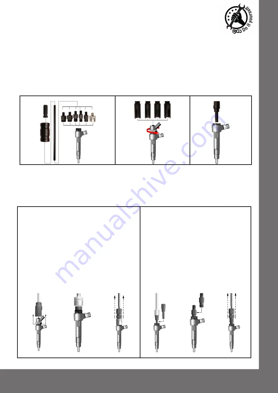
Adaptor
Sockets
Internal Hexagon
NOTE:
The technique required for removal of the injector will depend on which system is fitted to the
vehicle. Always use an external adaptor first if possible. If by using reasonable force the in je ct or cannot
be removed, use an internal adaptor. Before working on the fuel system, make sure that the fuel system is
not under pressure. Refer to the manufacturer's instruction manual on how to de-pressurise the system.
Disconnect the injector wires and connections as per the manufacturer's instructions. Remove any carbon
build up from around the injector. Remove the electrical unit from the injector.
OPERATION
External Thread Adaptor
Internal Thread Adaptor
1. Remove the electrical unit (see A).
2. Position the adapter with outside thread on top of
the injector (see B)
3. Connect sliding hammer to the adapter with
outside thread (see C).
4. The injector can be removed by using reasonable
force on the sliding hammer.
5. When an injector has been removed, it is
recommended that only a new or refurbished
injector is fitted.
6. Follow manufacturers fitting and safety
instructions.
1. Remove the electrical unit (see A).
2. Insert and turn anti-clockwise a special hex
socket to remove the inner sleeve (see D).
3. Screw the appropriate internal adaptor (5)
into the threads of the injector and tighten
with a suitable spanner (see E).
4. Screw the slide hammer onto the adaptor.
5. The injector can now be removed using
reasonable force on the slide hammer (see
F). Be prepared for the sudden release of
the injector from the cylinder head.
6. When an injector has been removed, it is
recommended that only a new or
refurbished injector is fitted.
7. Follow manufacturers fitting and safety
instructions.
A
B
C
D
E
F
NOTE:
To protect the threads, all fittings must be tightened.


