background image

14 -


LEM7 LEM8F Ver. 01

D811025A_01

INSTALLATION MANUAL

ENGLISH

WARNING:

 If the opening direction is not correct, invert the motor

connections no. 3 and 5 and connections no. 11 and 12 of the opening and
closing limit switches.

13) MOTOR TORQUE SETTING (SAFETY CLUTCH)

WARNING: Check that the impact force value measured at the
points established by the EN 12445 standard is lower than that
specified in the EN 12453 standard.

The setting must be carried out according to whatever is provided for by the
current safety standards. For this purpose, the motor torque needs to be set
in the following way:

Disconnect the mains power supply.

Remove the screws securing the gearmotor guard.

Use the fixed key provided to lock the motor shaft (fig.17 - ref. “A”). Using
the release knob, screw the self-locking nut (fig.17 - ref. “D”) to increase
the torque, or slacken it to decrease the torque.

Reconnect the power supply and, with the help of a torquemeter, check
that the motion stops at the mechanical resistance values set out by the
current standards.

Put the protection guard back on the gearmotor and secure it with its
screws.

 DANGER - The torque regulator must be calibrated before the

automation system is made to be operational.

14) EMERGENCY MANOEUVRE

Manual leaf opening is to be carried out in case of power supply failure or
automation inefficiency. Two types of knobs are available:
A) Pull-out knob
B) Personalised key-knob

Knob “A” 

(fig.18)

Insert the release knob in the appropriate seat, and rotate it clockwise
along its entire travel.

Push the gate leaf by hand.

In order to reset motor-driven operation or keep the gate locked on closing,
rotate the knob anticlockwise along its entire travel, move the leaf by hand
until it reaches its dragging point, remove the knob and keep it in a place
known to all users.

When the power supply comes back on, the automation device will resume
motor-driven operation.

Knob “B” 

(fig. 19-20)

In the case where a locking knob with a personalised key (fig.19-20) is used,
proceed as follows:

Insert the personalised key (fig.19) in knob lock, and rotate the knob
anticlockwise until a click is heard.

Rotate the release key clockwise along its entire travel (fig.20).

Push the leaf by hand. The personalised key cannot be pulled out until
motor-driven operation is reset.

In order to reset motor-driven operation, rotate the knob anticlockwise,
and rotate the key clockwise until it comes out.

Keep the key in a place known to all users.

15) INSTALLATION CHECK

Before the automation device finally becomes operational, scrupulously
check the following conditions:

Check that all the safety devices (limit microswitches, photocells, electric
edges etc) operate correctly.

Check that the rack and pinion are correctly meshed (minimum play 2mm).

Check that the pushing force of the gate is within the limits provided for by
the current standards.

Check that the opening and closing end-of-stroke runners are correctly
positioned and tightly secured.

Check the starting and stopping operations using the manual control.

Check the starting and stopping operations using the remote radio control.

Check the normal or customised operation logic.

16) AUTOMATION DEVICE USE

Since the automation device can be controlled both remotely and in sight,
by means of a radio control device or a button, all the safety devices must
be frequently checked in order to ensure their perfect efficiency.

WARNING! In the event of any safety device malfunction, request
immediate assistance from qualified personnel. Children must be
kept at a safe distance from the automation operation area.

17) AUTOMATION CONTROL

The use of this control device allows the gate to be opened and closed
automatically. There are different types of controls (manual, radio control,
magnetic card access etc.) depending on the installation requirements and
characteristics. For the various control systems, see the relevant instructions.

The installer undertakes to instruct the user about correct automa-
tion operation, also pointing out the actions to be taken in case of
emergency.

18) MAINTENANCE
WARNING! Before proceeding to any maintenance, disconnect the
mains power supply and, if the battery is fitted, one of its poles.

These are the check and maintenance operations to be carried out:

Check the condition of lubrication of the metal racks once a year.

Keep the sliding track always clean and free from debris.

Occasionally clean the photocell optical elements.

Have a qualified technician (installer) check the correct torque limit
setting.When any operational malfunction if found, and not resolved,
disconnect the mains power supply and request the assistance of a qualified
technician (installer). When the automation controller is out of service, you
can activate the manual release device (see paragraph on “

Emergency

manoeuvre

”) in order to set the pinion idling and therefore allow the gate

to be opened and closed by hand.

19) NOISE

The environmental noise produced by the gear-motor in normal operation
conditions is constant and does not exceed 70 dB (A).

21) SCRAPPING

Materials must be disposed of in conformity with the current regula-
tions.
In case of scrapping, the automation devices do not entail any particu-
lar risks or danger.  In case of materials to be recycled, these should be
sorted out by type (electrical components, batteries, copper, aluminium, plastic
etc.).

20) DISMANTLING

When the automation system is disassembled to be reassembled on
another site, proceed as follows:
• Disconnect the power supply and the entire external electrical installation.
• In the case where some of the components cannot be removed or are

damaged, they must be replaced.

21) MALFUNCTION: CAUSES and REMEDIES
21.1) The gate does not open. The motor does not turn.

1) Check that the photocells or the sensitive edges are not dirty, engaged,

or not aligned. Proceed accordingly.

2) Check that the electronic appliance is correctly supplied. Check the

integrity of the fuses.

3) Check that the functions are correct by means of the control unit diagnosing

LEDs (see relevant instructions).
Identify causes for faults, if any. If the LEDs show persisting start control,
check that no radio controls, start buttons or other control devices keep the
start contact activated (closed).

4) If the control unit does not work, it must be replaced.

If after having carried out the checks listed above the problem persists,
replace the actuator.

21.2) The gate does not open. The motor turns but the movement does
not take place.

1) The manual release is activated. Reset the power-driven operation.
2) Check that the gate had reached the mechanical end-of-stroke stops.

Release and move the gate manually, and reset the power-driven control.
Check and correct the end-of-stroke bracket position.

3) Check that the mechanical setting of the gate is not defective, for example

if the wheels are blocked or the rack is not aligned with the pinion, etc.

4) Check that the clutch does not slip. If it does, load it as described in the

relevant paragraph.
If after having carried out the checks listed above the problem persists,
replace the actuator.

WARNING! Correct controller operation is only ensured when the data
contained in the present manual are observed. The company is not to
be held responsible for any damage resulting from failure to observe
the standards relating to safety, installation and good technical
practice, as well as the instructions contained in the present manual.

The descriptions and illustrations contained in the present manual
are not binding. The Company reserves the right to make any altera-
tions deemed appropriate for the technical, manufacturing and com-
mercial improvement of the product, while leaving the essential
product features unchanged, at any time and without undertaking to
update the present publication.

Summary of Contents for LEM7

Page 1: ...CION INSTRUÇÕES DE USO E DE INSTALAÇÃO D811025A ver 01 18 03 05 I GB F D E P LEM7 LEM8F ACTUATOR FOR RACK SLIDING GATES ACTIONNEUR POUR PORTAILS COULISSANTS A CREMAILLERE AUTOMATIONEN FUER SHIEBEGITTERTORE MIT ZAHNSTANGE SERVOMOTOR PARA CANCELAS CORREDERAS DE CREMALLERA ACCIONADOR PARA PORTÖES DE CORRER A CREMALLERA ATTUATORE PER CANCELLI SCORREVOLI A CREMAGLIERA 8 027908 111586 ...

Page 2: ...2 LEM7 LEM8F Ver 01 D811025A_01 ...

Page 3: ... di rete Tenere pulito la guida di scorrimento le ottiche delle fotocellule ed i dispositivi di segnalazione luminosa Controllare che rami e arbusti non disturbino i dispositivi di sicurezza fotocellule o il movimento dell anta Periodicamente controllare la lubrificazione della cremagliera Se in materiale plastico non deve essere lubrificata Perqulsiasiinterventodirettoall automazione avvalersidip...

Page 4: ...technician installer Before proceeding to any external cleaning operation disconnect the mains powers supply and at least one of the battery pole if fitted Keep the photocell optical components and luminous signal indication devicesclean Checkthatthesafetydevices photocells arenotobscured by branches or shrubs Foranydirectassistancetotheautomationsystem requesttheassistance of a qualified technici...

Page 5: ...au moins un pôle des batteries Nettoyer les optiques des cellules photoélectriques et les dispositifs de signalisation lumineuse S assurer que des branches ou des arbustes ne dérangent pas les dispositifs de sécurité cellules photoélectriques Pourtouteinterventiondirectesurlamotorisation s adresseràdupersonnel qualifié installateur Chaque année faire contrôler la motorisation par du personnel qual...

Page 6: ...en Vor jeder Außenreinigung die Stromversorgung unterbrechen und falls vorhanden zumindest einen Batteriepol abklemmen Halten Sie die Linsen der Lichtschranken und die Blinkleuchte sauber Prüfen Sie ob Äste oder Gesträuch die Sicherheitsvorrichtun gen beeinträchtigen können Lichtschranke Wenn eine Arbeit unmittelbar an der Anlage erforderlich ist wenden Sie sich hierzu an fachkundiges Personal Ins...

Page 7: ...piezaexterna cortarelsuministro de corriente y si está presente el kit de baterías tampón desconectar al menos un polo de las baterías Mantenerlimpiaslaslentesdelasfotocélulasylosdispositivosdeseñalización luminosa Controlar que ramas o arbustos no interfieran con los dispositivos de seguridad fotocélulas Si resulta necesario efectuar una intervención directa en el automatismo llamar a personal cu...

Page 8: ...qualquer operação de limpeza externa interrompa a alimentação de rede e se presente pelo menos um pólo das baterias Mantenhalimpasasópticasdasfotocélulaseosdispositivosdesinalização luminosa Controle que ramos e arbustos não disturbem os dispositivos de segurança fotocélulas Para qualquer intervenção directa na automatização sirva se de pessoal qualificado instalador Faça controlar anualmente a au...

Page 9: ...lla Ditta Istruire l utilizzatore dell impianto per quanto riguarda i sistemi di comando applicati e l esecuzione dell apertura manuale in caso di emergenza Non permettere a persone e bambini di sostare nell area d azione dell au tomazione Non lasciare radiocomandi o altri dispositivi di comando alla portata dei bambini onde evitare azionamenti involontari dell automazione L utilizzatore deve evit...

Page 10: ... corretto ingranamento 9 FINECORSA ELETTROMECCANICI L operazione va eseguita con sblocco di emergenza attivato e senza alimentazione di rete I pattini che comandano i finecorsa vanno posizionati alle estremità della cremagliera Spingere manualmente il cancello in completa apertura Posizionare il pattino finecorsa di apertura fig 11 in modo che intercetti la leva di comando del micro e che lo facci...

Page 11: ...o manuale telecomando controllo accessi con badge magnetico ecc secondo le necessità e le caratteristiche dell installazione Per i vari sistemi di comando vedere le istruzioni relative 18 MANUTENZIONE ATTENZIONE Per qualsiasi manutenzione all installazione togliere l ali mentazione di rete I punti che necessitano di controlli e manutenzione sono Per le cremagliere in metallo annualmente verificare...

Page 12: ...gesetc whichareneeded to protect the area from any danger caused by squashing conveying and shearing Position at least one luminous signal indication device blinker where it can be easily seen and fix a Warning sign to the structure The Company declines all responsibility with respect to the automation safety and correct operation when other manufacturers components are used Only use original part...

Page 13: ...ied out by a competent person who must be provided with all the personal protection equipment required by the current safety standards 8 PINION ADJUSTMENT Having finished fixing the rack the rack pinion play needs to be adjusted to approximately 2mm fig 6 this is obtained by slackening the four M10 nuts under the gearmotor base by approximately 2mm and then securing the four upper nuts Make sure t...

Page 14: ...he installation requirements and characteristics For the various control systems see the relevant instructions The installer undertakes to instruct the user about correct automa tion operation also pointing out the actions to be taken in case of emergency 18 MAINTENANCE WARNING Before proceeding to any maintenance disconnect the mains power supply and if the battery is fitted one of its poles Thes...

Page 15: ...euses etc nécessaires à protéger la zone des dangers d écrasement d entraînement de cisaillement Appliquer au moins un dispositif de signalisation lumineuse feu clignotant en position visible fixer à la structure un panneau de Attention La Société décline toute responsabilité en matière de sécurité et de bon fonctionnement de la motorisation si des composants d autres producteurs sont utilisés Uti...

Page 16: ... les normes de sécurité en vigueur 8 REGLAGE DU PIGNON Une fois la fixation de la crémaillère terminée il faudra régler le jeu crémaillère pignon qui devra être de 2mm environ fig 6 dans ce but desserrer d environ 2mm les quatre écrous M10 sous la base du motoréducteur et fixer ensuite les quatre écrous supérieurs Assurer l alignement et le centrage de la crémaillère pignon fig 10 ATTENTION Se rap...

Page 17: ... personnel qualifié Il est recommandé de tenir les enfants loin du rayon d action de la motorisation 17 COMMANDE L utilisation de la motorisation permet l ouverture et la fermeture du portail de manière motorisée La commande peut être de type différent manuelle avec radio commande contrôle des accès avec badge magnétique etc selon les besoins et les caractéristiques de l installation Pour les diff...

Page 18: ...gen in Reich weite von Kindern liegenlassen Sie könnten die Anlage versehentlich in Gang setzen DerBetreiberhatjedenVersucheinesEingriffesoderderReparaturzuunterlassen Nur entsprechend qualifizierte Fachleute sind hierzu befugt Alles was nicht ausdrücklich in dieser Anleitung genannt ist ist untersagt 3 TECHNISCHE DATEN Stromversorgung Einphasig 230V 10 50Hz Motordrehzahl 1400min 1 Leistungsaufnah...

Page 19: ... Hand vollständig das Tor Den Kontaktschlitten für den Öffnungsendschalter Abb 11 so positio nieren daß er den Steuerhebel des Mikroschalters abfängt und diesen auslösen läßt WenndierichtigeLagegefundenist dieSchraubendesKontaktschlittensanziehen Das Tor von Hand ganz schließen Den Kontaktschlitten für den Schließungsendschalter Abb 11 so posi tionieren daß er den Steuerhebel des Mikroschalters ab...

Page 20: ...ozellen Lassen Sie von Fachleuten Installateur die korrekte Einstellung des Drehmomentbegrenzers prüfen Bei jeder nicht behobenen Betriebsstörung die Stromversorgung des Systems unterbrechen und Fachleute Installateur hinzuziehen Während die Anlage außer Betrieb ist läßt sich die Notfallentsperrung aktivieren siehe Abschnitt Notfallbedienung Dadurch wird das Ritzel gelöst und das Tor läßt sich von...

Page 21: ...ales al realizar cualquier operación de mantenimiento o reparación No modificar ningún componente del automatismo si antes no se ha sido expresamente autorizado por la Empresa Instruir al usuario del equipo sobre los sistemas de mando aplicados y la ejecución de la apertura manual en caso de emergencia No permitir que personas o niños estacionen en el campo de acción del automa tismo No dejar radi...

Page 22: ...el mecanismo de desbloqueo de emergencia activado y sin alimentación de red En el caso de que haya baterías habrá que desconectar al menos un polo Los patines que accionan a los fines de carrera deben colocarse en los extremos de la cremallera A continuación hay que realizar lo siguiente Empujar a mano la cancela hasta que quede completamente abierta Colocar el patín de fin de carrera de apertura ...

Page 23: ...véanselasinstrucciones correspondientes El instalador se compromete a instruir al usuario del automatismo sobre el uso correcto del mismo evidenciando las operaciones que se tendrán que efectuar en caso de emergencia 18 MANTENIMIENTO ATENCION Antes de realizar cualquier operación de mantenimiento en la instalación hay que cortar el suministro de corriente del sistema y si hay batería desconectar u...

Page 24: ...sa lampejante numa posição visível fixe à estrutura um cartaz de Atenção A Empresa declina qualquer responsabilidade relativa à segurança e ao bom funcionamento da automatização se forem utilizados componentes de outros produtores Useexclusivamentepeçasoriginaisparaqualquermanutençãooureparação Não efectue nenhuma modificação nos componentes da automatização se não for expressamente autorizada pel...

Page 25: ...ULAÇÃO DO PINHÃO Terminada a fixação da cremalheira é necessário regular o jogo cremalheira pinhãoquedeveserdeaproximadamente2mm fig 6 istoobtém sedesaper tando por mais ou menos 2 mm as quatro porcas M10 por baixo da base do motoredutor e fixando em seguida as quatro porcas superiores Assegure o alinhamento e a centragem da cremalheira pinhão fig 10 ATENÇÃO Recorde se que a duração da cremalheira...

Page 26: ...s de segurança intervenha rapidamente servindose mesmo de pessoal qualificado Recomendase de manter as crianças a devida distância do raio de acção da automatização 17 COMANDO A utilização da automatização consente a abertura e o fecho do portão em modomotorizado Ocomandopodeserdetipodiverso manual telecomando controlo dos acessos com cartão magnético etc segundo as necessidades e as característic...

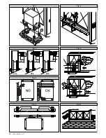
Page 27: ...LEM7 LEM8F Ver 01 27 D811025A_01 Fig 1 Fig 2 Fig 4 Fig 3 Fig 5 250 350 400 260 131 118 1 5 5 5 0 5 5 2 5 0 3 0 0 1 5 5 260 132 55 2 2 4 1 L F 2mm Min 100mm Min 25 50 25 P S F C FM FM R M ...

Page 28: ...28 LEM7 LEM8F Ver 01 D811025A_01 Fig 6 Fig 8 Fig 7 Fig 9 Fig 11 Fig 12 Fig 10 CFZ CPZ CVZ 37 30 12 20 30 32 28 22 22 DX SX Min 50mm NO OK S ...

Page 29: ...LEM7 LEM8F Ver 01 29 D811025A_01 Fig 13 Fig 14 C QR 3x1mm2 T 3x1 5mm2 2x1 5mm2 3x1 5mm2 RG58 AL M I P S 3 x 1 5 m m 2 3x1 5mm2 Fre Fte 4x1mm 2 2x1 5mm2 ...

Page 30: ...30 LEM7 LEM8F Ver 01 D811025A_01 Fig 18 Fig 19 Fig 20 Fig 16 Fig 17 Fig 15 18 17 16 15 14 13 12 11 10 9 8 EBP 7 L N M 5 4 3 2 1 SW C NC SW O NC PHOT NC BL ST NC NA 0V II RC 24V AC ANTENN G D A P2 P1 ...

Page 31: ...LEM7 LEM8F Ver 01 31 D811025A_01 ...

Page 32: ......

Reviews: