BFT LEM7 Installation And User Manual Download Page 13

LEM7 LEM8F Ver. 01 - 

13

D811025A_01

INSTALLATION MANUAL

ENGLISH

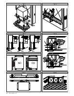
5.2) Other positions

The gearmotor can be positioned in different ways. As an example, fig.5
illustrates a particular type of installation. In the case where the gearmotor
is not fixed on the  level of the sliding track (

Standard position

), you must

ensure that the gearmotor is tightly secured also in relation to the gate
position, so as to maintain a correct play (1-2mm) between rack and
pinion. The current safety standards with respect to persons, animals and
things must be strictly observed, and in particular risks of accidents due to
squashing in the area of pinion-rack meshing, as well as other mechanical
risks, must be carefully avoided.  

All the critical spots must be protected

by safety devices in compliance with the current prescriptions.

6) GEARMOTOR FITTING

After the concrete casting has hardened, look at fig. 6 and proceed as follows

Position an M10 nut in each of the tie rods, keeping them at a distance of
at least 25mm from the base, so that the gearmotor can be lowered after
installation or the play between pinion and rack can be subsequently
adjusted.

Position a “P” plate supplied with each pair of tie rods, and use a level to
adjust the surface both ways.

Remove the casing and screw-cover guard from the gearmotor, and position
the reduction gear unit over the four tie rods, with the pinion facing the
gate.

Position the four washers and screw the four locking nuts on the gearmotor.

Adjust the depth of the gearmotor by making it slide along the appropriate
slots provided in the base, keep an adequate distance between pinion and
gate for the type of rack to be fitted, and secure the gearmotor. The rack
teeth must mesh with the pinion over their whole width.
The section on “Rack fitting” gives the measurements and installation
method of the most widely used types of rack.

7) RACK FITTING

A rack having a 4 tooth pitch must be fitted to the gate. As far as the length
is concerned, this must include the passage space, as well as the space for
securing the brackets activating the limit microswitches, and for the pinion
meshing section. There are different types of rack, each one differing in
terms of capacity and gate fixing method. The Company markets three
types of racks, which are.

7.1) Mod. CFZ

 (Fig.7).

Galvanised iron rack - 22x22mm section - supplied in 2 - metre lengths -
capacity over 2000kg (

 20000N). First weld these pieces onto an adequate

iron angle bar and then weld the lot to the gate. Besides maintaining the
distance between the rack and the side of the gate, the angle bar makes it
easy to fix the rack to the gate, even when the latter is subject to slight side
slipping. When join welding the various rack pieces, you are advised to
arrange a section of rack as in (fig.8) to ensure a correct pitch along the
entire length of the rack.

7.2) Mod. CPZ

 (Fig.7).

Plastic rack - 22x22mm section - supplied in 1- metre lengths - max.
capacity 500kg (

 5000N). This model is to be fixed to the gate by means

of normal or self-threading screws. Also in this case, you are advised to
insert a section of rack the other way round in the joint between the various
pieces, so as to maintain the correct tooth pitch. This type of rack is quieter
and allows height adjustments to be made even after having been fixed,
using the slots provided.

7.3) Mod. CVZ

 (Fig.7)

Galvanised iron rack - 30x12mm section - supplied in 1 - metre lengths -
threaded spacers to be welded - max. capacity 2000kg (

 20000N). Having

fixed the spacers in the middle of each of the slots in the various rack pieces,
weld the spacers to the gate. Also in this case, arrange a section of rack the
other way round in the joining points of the various rack pieces to ensure a
correct tooth pitch. The screws which fix the rack to the spacers allow the rack
to be adjusted in height.

7.4) Rack fitting

To fit the rack, proceed as follows:

Activate the emergency release by rotating the appropriate release knob
(See paragraph “Emergency manoeuvre”).

Rest the rack end on the control pinion and secure it (by welding or using
screws) in correspondence with the pinion, while sliding the gate along by
hand (fig. 9).

In the case of incorrect gate alignment (excessive side curving) which
cannot be corrected, place a few shims between the rack and gate in order
to ensure continuous centring of the rack with respect to the pinion (fig.
10).

DANGER - The welding operation is to be carried out by a competent
person who must be provided with all the personal protection
equipment required by the current safety standards.
8) PINION ADJUSTMENT

Having finished fixing the rack, the rack-pinion play needs to be adjusted to
approximately 2mm (fig.6): this is obtained by slackening the four M10 nuts
under the gearmotor base by approximately 2mm, and then securing the four

upper nuts. Make sure that the rack and pinion are aligned and centred
(fig.10).

WARNING - Remember that the rack and pinion life strictly depends on
their correct meshing.

9) ELECTROMECHANICAL LIMITING DEVICES

The operation must be carried out with the emergency release activated
and the mains power supply disconnected. The runners which control the
limiting devices are to be positioned at both ends of the rack.
-

Push the gate fully open by hand.

-

Position the opening end-of-stroke runner (fig.11) so that it intercepts the
microswitch control lever and makes it trigger. Having identified the correct
position, tighten the runner screws.

-

Push the gate fully closed by hand.

-

Position the closing end-of-stroke runner (fig.11) so that it intercepts the
microswitch control lever and makes it trigger. Having identified the correct
position, tighten the runner screws.

-

The runners must lock the gate before this intercepts the mechanical
backstops placed on the track. The closing end-of-stroke runner adjustment
must be made in such a way as to leave a clearance of approximately
50mm between the gate and the fixed swing leaf, as prescribed by the
current safety standards, otherwise fit an electric edge at least 50mm thick
(fig.12).

10) GATE BACKSTOPS
DANGER - The gate must be provided with mechanical backstops, both
on opening and closing, in order prevent it from coming out of the upper
guide (fig.13); the backstops must be tightly secured to the ground, a
few centimetres beyond the electrical stop point.

11) ELECTRICAL INSTALLATION SETUP

Lay out the electrical installation as shown in fig.14 with reference to the CEI
64-8 and IEC364 provisions complying with the HD384 and other national
standards in force for electrical installation.

WARNING!  For connection to the mains, use a multipolar cable
having a minimum cross section of 3x1.5 mm

2

 and complying with the

current  standards. (For example, if the cable is not protected, it must
be at least equal to H07 RN-F, whereas if it is protected it must be at
least equal to H07 VV-F with a 3x1.5 sq mm

2

 cross section).

Connect the control and safety devices in compliance with the previously
mentioned technical installation standards. The cables (mains and auxil-
iary) must be distinctly separated.  Fig.14 shows the number of connections
and their cross sections for a length of approximately 100 metres; for
greater lengths, calculate the cross section for the true automation load.

The main automation components are (fig.14):

I

Type-approved adequately rated omnipolar circuit-breaker with
at least 3-mm contact opening, provided with protection against
overloads and short circuits, suitable for cutting out automation
from the mains. If not already installed, place a type-approved
omnipolar circuit-breaker with a 0.03A threshold just before the
automation system.

S

Key selector.

AL

Blinker with tuned antenna.

M

Actuator

P

Wall-mounted pushbutton panel.

Fte, Fre

Pair of external photocells.

T

1-2-4 channel transmitter.

11) TERMINAL BOARD CONNECTIONS

First pass the appropriate electric cables through the raceways and fix the
various automation components to the chosen points, then connect them
following the directions and diagrams contained in the control unit instruction
manual.
Carry out phase, neutral and (compulsory) earth connections. The protection
wire (earth) with yellow/green insulating sheath must be connected to the
appropriate terminals marked by their symbol.
Operate the automation only after having connected and checked all the
safety devices.
A description of the terminals of MIZAR control unit installed on the actuator
is given below (fig. 16).

1-2

Single-phase power supply: (1=L) (2=N)

3-4-5 Motor connection (4 common, 3-5 operation and capacitor)
4-1

Blinker connection (mains voltage)

7-8

Open-Close push button, key selector (N.O.)

7-9

Stop push button (N.C.). If not used, leave jumped.

7-10 Photocell input or rubber skirt (N.C.). If not used, leave jumped.

Opening limit switch (N.C.). If not used, leave jumped.
Closing limit switch (N.C.). If not used, leave jumped.

13-14 24 Vac 180mA max output - power supply to photocells or other devices
15-16 Second radio channel output of twin-channel receiver board

Antenna input for radio receiver board (17 signal - 18 braid).
GND terminal

Summary of Contents for LEM7

Page 1: ...CION INSTRUÇÕES DE USO E DE INSTALAÇÃO D811025A ver 01 18 03 05 I GB F D E P LEM7 LEM8F ACTUATOR FOR RACK SLIDING GATES ACTIONNEUR POUR PORTAILS COULISSANTS A CREMAILLERE AUTOMATIONEN FUER SHIEBEGITTERTORE MIT ZAHNSTANGE SERVOMOTOR PARA CANCELAS CORREDERAS DE CREMALLERA ACCIONADOR PARA PORTÖES DE CORRER A CREMALLERA ATTUATORE PER CANCELLI SCORREVOLI A CREMAGLIERA 8 027908 111586 ...

Page 2: ...2 LEM7 LEM8F Ver 01 D811025A_01 ...

Page 3: ... di rete Tenere pulito la guida di scorrimento le ottiche delle fotocellule ed i dispositivi di segnalazione luminosa Controllare che rami e arbusti non disturbino i dispositivi di sicurezza fotocellule o il movimento dell anta Periodicamente controllare la lubrificazione della cremagliera Se in materiale plastico non deve essere lubrificata Perqulsiasiinterventodirettoall automazione avvalersidip...

Page 4: ...technician installer Before proceeding to any external cleaning operation disconnect the mains powers supply and at least one of the battery pole if fitted Keep the photocell optical components and luminous signal indication devicesclean Checkthatthesafetydevices photocells arenotobscured by branches or shrubs Foranydirectassistancetotheautomationsystem requesttheassistance of a qualified technici...

Page 5: ...au moins un pôle des batteries Nettoyer les optiques des cellules photoélectriques et les dispositifs de signalisation lumineuse S assurer que des branches ou des arbustes ne dérangent pas les dispositifs de sécurité cellules photoélectriques Pourtouteinterventiondirectesurlamotorisation s adresseràdupersonnel qualifié installateur Chaque année faire contrôler la motorisation par du personnel qual...

Page 6: ...en Vor jeder Außenreinigung die Stromversorgung unterbrechen und falls vorhanden zumindest einen Batteriepol abklemmen Halten Sie die Linsen der Lichtschranken und die Blinkleuchte sauber Prüfen Sie ob Äste oder Gesträuch die Sicherheitsvorrichtun gen beeinträchtigen können Lichtschranke Wenn eine Arbeit unmittelbar an der Anlage erforderlich ist wenden Sie sich hierzu an fachkundiges Personal Ins...

Page 7: ...piezaexterna cortarelsuministro de corriente y si está presente el kit de baterías tampón desconectar al menos un polo de las baterías Mantenerlimpiaslaslentesdelasfotocélulasylosdispositivosdeseñalización luminosa Controlar que ramas o arbustos no interfieran con los dispositivos de seguridad fotocélulas Si resulta necesario efectuar una intervención directa en el automatismo llamar a personal cu...

Page 8: ...qualquer operação de limpeza externa interrompa a alimentação de rede e se presente pelo menos um pólo das baterias Mantenhalimpasasópticasdasfotocélulaseosdispositivosdesinalização luminosa Controle que ramos e arbustos não disturbem os dispositivos de segurança fotocélulas Para qualquer intervenção directa na automatização sirva se de pessoal qualificado instalador Faça controlar anualmente a au...

Page 9: ...lla Ditta Istruire l utilizzatore dell impianto per quanto riguarda i sistemi di comando applicati e l esecuzione dell apertura manuale in caso di emergenza Non permettere a persone e bambini di sostare nell area d azione dell au tomazione Non lasciare radiocomandi o altri dispositivi di comando alla portata dei bambini onde evitare azionamenti involontari dell automazione L utilizzatore deve evit...

Page 10: ... corretto ingranamento 9 FINECORSA ELETTROMECCANICI L operazione va eseguita con sblocco di emergenza attivato e senza alimentazione di rete I pattini che comandano i finecorsa vanno posizionati alle estremità della cremagliera Spingere manualmente il cancello in completa apertura Posizionare il pattino finecorsa di apertura fig 11 in modo che intercetti la leva di comando del micro e che lo facci...

Page 11: ...o manuale telecomando controllo accessi con badge magnetico ecc secondo le necessità e le caratteristiche dell installazione Per i vari sistemi di comando vedere le istruzioni relative 18 MANUTENZIONE ATTENZIONE Per qualsiasi manutenzione all installazione togliere l ali mentazione di rete I punti che necessitano di controlli e manutenzione sono Per le cremagliere in metallo annualmente verificare...

Page 12: ...gesetc whichareneeded to protect the area from any danger caused by squashing conveying and shearing Position at least one luminous signal indication device blinker where it can be easily seen and fix a Warning sign to the structure The Company declines all responsibility with respect to the automation safety and correct operation when other manufacturers components are used Only use original part...

Page 13: ...ied out by a competent person who must be provided with all the personal protection equipment required by the current safety standards 8 PINION ADJUSTMENT Having finished fixing the rack the rack pinion play needs to be adjusted to approximately 2mm fig 6 this is obtained by slackening the four M10 nuts under the gearmotor base by approximately 2mm and then securing the four upper nuts Make sure t...

Page 14: ...he installation requirements and characteristics For the various control systems see the relevant instructions The installer undertakes to instruct the user about correct automa tion operation also pointing out the actions to be taken in case of emergency 18 MAINTENANCE WARNING Before proceeding to any maintenance disconnect the mains power supply and if the battery is fitted one of its poles Thes...

Page 15: ...euses etc nécessaires à protéger la zone des dangers d écrasement d entraînement de cisaillement Appliquer au moins un dispositif de signalisation lumineuse feu clignotant en position visible fixer à la structure un panneau de Attention La Société décline toute responsabilité en matière de sécurité et de bon fonctionnement de la motorisation si des composants d autres producteurs sont utilisés Uti...

Page 16: ... les normes de sécurité en vigueur 8 REGLAGE DU PIGNON Une fois la fixation de la crémaillère terminée il faudra régler le jeu crémaillère pignon qui devra être de 2mm environ fig 6 dans ce but desserrer d environ 2mm les quatre écrous M10 sous la base du motoréducteur et fixer ensuite les quatre écrous supérieurs Assurer l alignement et le centrage de la crémaillère pignon fig 10 ATTENTION Se rap...

Page 17: ... personnel qualifié Il est recommandé de tenir les enfants loin du rayon d action de la motorisation 17 COMMANDE L utilisation de la motorisation permet l ouverture et la fermeture du portail de manière motorisée La commande peut être de type différent manuelle avec radio commande contrôle des accès avec badge magnétique etc selon les besoins et les caractéristiques de l installation Pour les diff...

Page 18: ...gen in Reich weite von Kindern liegenlassen Sie könnten die Anlage versehentlich in Gang setzen DerBetreiberhatjedenVersucheinesEingriffesoderderReparaturzuunterlassen Nur entsprechend qualifizierte Fachleute sind hierzu befugt Alles was nicht ausdrücklich in dieser Anleitung genannt ist ist untersagt 3 TECHNISCHE DATEN Stromversorgung Einphasig 230V 10 50Hz Motordrehzahl 1400min 1 Leistungsaufnah...

Page 19: ... Hand vollständig das Tor Den Kontaktschlitten für den Öffnungsendschalter Abb 11 so positio nieren daß er den Steuerhebel des Mikroschalters abfängt und diesen auslösen läßt WenndierichtigeLagegefundenist dieSchraubendesKontaktschlittensanziehen Das Tor von Hand ganz schließen Den Kontaktschlitten für den Schließungsendschalter Abb 11 so posi tionieren daß er den Steuerhebel des Mikroschalters ab...

Page 20: ...ozellen Lassen Sie von Fachleuten Installateur die korrekte Einstellung des Drehmomentbegrenzers prüfen Bei jeder nicht behobenen Betriebsstörung die Stromversorgung des Systems unterbrechen und Fachleute Installateur hinzuziehen Während die Anlage außer Betrieb ist läßt sich die Notfallentsperrung aktivieren siehe Abschnitt Notfallbedienung Dadurch wird das Ritzel gelöst und das Tor läßt sich von...

Page 21: ...ales al realizar cualquier operación de mantenimiento o reparación No modificar ningún componente del automatismo si antes no se ha sido expresamente autorizado por la Empresa Instruir al usuario del equipo sobre los sistemas de mando aplicados y la ejecución de la apertura manual en caso de emergencia No permitir que personas o niños estacionen en el campo de acción del automa tismo No dejar radi...

Page 22: ...el mecanismo de desbloqueo de emergencia activado y sin alimentación de red En el caso de que haya baterías habrá que desconectar al menos un polo Los patines que accionan a los fines de carrera deben colocarse en los extremos de la cremallera A continuación hay que realizar lo siguiente Empujar a mano la cancela hasta que quede completamente abierta Colocar el patín de fin de carrera de apertura ...

Page 23: ...véanselasinstrucciones correspondientes El instalador se compromete a instruir al usuario del automatismo sobre el uso correcto del mismo evidenciando las operaciones que se tendrán que efectuar en caso de emergencia 18 MANTENIMIENTO ATENCION Antes de realizar cualquier operación de mantenimiento en la instalación hay que cortar el suministro de corriente del sistema y si hay batería desconectar u...

Page 24: ...sa lampejante numa posição visível fixe à estrutura um cartaz de Atenção A Empresa declina qualquer responsabilidade relativa à segurança e ao bom funcionamento da automatização se forem utilizados componentes de outros produtores Useexclusivamentepeçasoriginaisparaqualquermanutençãooureparação Não efectue nenhuma modificação nos componentes da automatização se não for expressamente autorizada pel...

Page 25: ...ULAÇÃO DO PINHÃO Terminada a fixação da cremalheira é necessário regular o jogo cremalheira pinhãoquedeveserdeaproximadamente2mm fig 6 istoobtém sedesaper tando por mais ou menos 2 mm as quatro porcas M10 por baixo da base do motoredutor e fixando em seguida as quatro porcas superiores Assegure o alinhamento e a centragem da cremalheira pinhão fig 10 ATENÇÃO Recorde se que a duração da cremalheira...

Page 26: ...s de segurança intervenha rapidamente servindose mesmo de pessoal qualificado Recomendase de manter as crianças a devida distância do raio de acção da automatização 17 COMANDO A utilização da automatização consente a abertura e o fecho do portão em modomotorizado Ocomandopodeserdetipodiverso manual telecomando controlo dos acessos com cartão magnético etc segundo as necessidades e as característic...

Page 27: ...LEM7 LEM8F Ver 01 27 D811025A_01 Fig 1 Fig 2 Fig 4 Fig 3 Fig 5 250 350 400 260 131 118 1 5 5 5 0 5 5 2 5 0 3 0 0 1 5 5 260 132 55 2 2 4 1 L F 2mm Min 100mm Min 25 50 25 P S F C FM FM R M ...

Page 28: ...28 LEM7 LEM8F Ver 01 D811025A_01 Fig 6 Fig 8 Fig 7 Fig 9 Fig 11 Fig 12 Fig 10 CFZ CPZ CVZ 37 30 12 20 30 32 28 22 22 DX SX Min 50mm NO OK S ...

Page 29: ...LEM7 LEM8F Ver 01 29 D811025A_01 Fig 13 Fig 14 C QR 3x1mm2 T 3x1 5mm2 2x1 5mm2 3x1 5mm2 RG58 AL M I P S 3 x 1 5 m m 2 3x1 5mm2 Fre Fte 4x1mm 2 2x1 5mm2 ...

Page 30: ...30 LEM7 LEM8F Ver 01 D811025A_01 Fig 18 Fig 19 Fig 20 Fig 16 Fig 17 Fig 15 18 17 16 15 14 13 12 11 10 9 8 EBP 7 L N M 5 4 3 2 1 SW C NC SW O NC PHOT NC BL ST NC NA 0V II RC 24V AC ANTENN G D A P2 P1 ...

Page 31: ...LEM7 LEM8F Ver 01 31 D811025A_01 ...

Page 32: ......

Reviews: