


24
Multifunction Control Panel
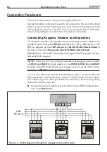
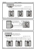
Figure 2.2 - Wiring diagram: Connecting 3 Keypads to the Control panel
Connecting Peripherals
This section describes the wiring of the peripheral devices.
Shielded conductor cable must be used for all connections. One end of the shield
must be connected to the Control panel, as shown in the wiring diagrams. Each
wiring diagrams refers to a specific device type (Keypad, Key/Card Reader,
Sensor or Signalling device) and shows the respective terminals.
Connecting Keypads, Readers and Expanders
The Keypads, Readers and Expanders (Input and Output) must be connected in
parallel to the
Control panel
BPI
Bus
(terminals 1[
+
], 2[
C
], 3[
R
] and 4[
–
]). The
BPI bus supports up to
24 BPI devices
(12 for KYO16D Control Panel)
in
all, but not more than
8 Keypads
(4 for KYO16D Control Panel)
.
IMPORTANT - KYO16D Control Panel manages all LCD keypads and only
Alison/8L LED keypad.
NOTE:
For Kyo4-8-32, this Control panel does not manage Lines L1 and L2
on
MIA/S
and
MIA/D
Keypads, and Line L1 on
OMNIA/TAST-R
and
ALISON
Keypads. KYO16D Control Panel does manage only L1 Line of LCD keypads,
but to use a
10Kohm
resistor for balanced line.
11.5V or over must be present across terminals [
+
] and [
–
], in order to allow the
BPI peripherals to operate properly. Owing to Voltage drops and stray capaci-
tance induced by the Control panel BPI bus connections, the following wiring
limitations must be respected:
the maximum wire length between the Main Unit the BPI peripheral must
not exceed
500 metres
;
3
11
8.
3907
(; &
(6&
35 *
21
5( 6
2))
Summary of Contents for KYO 32 M
Page 1: ...0 1 7 167 7 21 0 18 ...
Page 10: ...10 Multifunction Control Panel The NC2 TAST LED Keypad Figure 1 3 The NC2 TAST LED Keypad D D ...
Page 71: ...71 Section 3 Programming from PC 5 11 6 0 1 2 3 1 4 3 3 5 2 3 0 1 2 3 ...
Page 88: ...ISTISBLEUNKYO 2 6 160108 P70 17 6 85 7 6 U O 01 02 5HF FOLQ LQ RU WLRQ ...


