


18
Multifunction Control Panel
tooth on the Snatch bracket [
61
]. Using a screw, secure the Snatch bracket
to the wall.
A
In order to comply with the standards outlined in Performance Level 11 of
the IMQ-SECURITY SYSTEM certification, Readers must be fitted with Snatch
Microswitches.
5
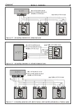
. Using the cable [
70
], complete the connections to the Control panel BPI
Bus.
6
. Assign the Addresses to all the peripheral devices (refer to
‘Addressing
Devices’
, further on in this section).
7
. Reattach the frontplate.
PROXI Readers must be located at least 50 cm apart.
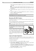
Mounting ECLIPSE Readers
ECLIPSE Key Readers can be flush mounted on standard electricity outlet
boxes (refer to Table 1.3).
Before mounting the Reader, complete the connections between the ECLIPSE
terminal board [
53
] and Control panel BPI Bus.
A
In order to comply with the standards outlined in Performance Level 11 of the IMQ-
SECURITY SYSTEM certification, Readers must be fitted with Snatch Microswitches.
ECLIPSE Readers must be located at least
50 cm apart.
Using the Address Microswitches [
51
], assign
the Reader Address
(refer to
‘Addressing De-
vices’
, further on in this section)
. For security
reasons, outdoor flush-mounted Key Readers
must be fitted with tamper protection (see Fig-
ure above).
Input and Output Expanders
The Input and Output Expanders must be located as near as possible to the
peripherals they are connected to. The Input and Output Expanders boxes can
be surface or flush mounted.
To install the Expanders:
1
. Remove the Wire entry knockout ([
57
] or [
85
], as required.
2
.
For Surface Mounting:
drill the holes for the back box and Snatch
bracket (screw locations [
84
] and [
61
] respectively).
For Surface Mounting on Mod.503 boxes or similar:
drill the holes for
the back box and Snatch bracket (screw locations [
83
] and [
61
] respectively).
For Flush Mounting:
No drilling is necessary.
3
. Pull the wires through the wire entry.
Summary of Contents for KYO 32 M
Page 1: ...0 1 7 167 7 21 0 18 ...
Page 10: ...10 Multifunction Control Panel The NC2 TAST LED Keypad Figure 1 3 The NC2 TAST LED Keypad D D ...
Page 71: ...71 Section 3 Programming from PC 5 11 6 0 1 2 3 1 4 3 3 5 2 3 0 1 2 3 ...
Page 88: ...ISTISBLEUNKYO 2 6 160108 P70 17 6 85 7 6 U O 01 02 5HF FOLQ LQ RU WLRQ ...


