


19
Section 2 - Installation
! ,55,67
'0+
,
!
"
! "
/ / / / / / / /
/0 /0 /0 /0 /0 /0 /0 /0
!
/ / / /
/0 /0 /0 /0
/ / / /
/0 /0 /0 /0
"
/ /
/0 /0
/ /
/0 /0
/ /
/0 /0
/ /
/0 /0
/
/0
/
/0
/
/0
/
/0
/
/0
/
/0
/
/0
/
/0
!! ,55,67
0+
,
!
"
! "
8
/ / / / / / / / / / / / / / / /
!
/ / / / / / / /
/0 /0 /0 /0 /0 /0 /0 /0
"
/ / / /
/0 /0 /0 /0
/ / / /
/0 /0 /0 /0
/ /
/0 /0
/ /
/0 /0
/ /
/0 /0
/ /
/0 /0
/
/0
/
/0
/
/0
/
/0
/
/0
/
/0
/
/0
/
/0
4
. Attach the back box and Snatch bracket.
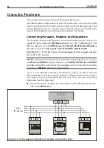
5
. Replace the Expander Module [
80
] (see Figure 1.6), ensure that it is held
firmly in place by the PCB clips [
58
] then, using the two screws [
81
], secure
it to the backplate.
6
. Complete the connections on the terminal board [
53
].
7
. Using the Microswitch [
51
], assign the Expander address
(refer to
‘Ad-
dressing Devices’
, further on in this section)
.
8
. If necessary, remove the Jumper [
78
] in order to enable Tamper and Snatch
Microswitches.
9
. Using the Jumper [
77
], set the Buzzer Mode.
10
. Using the 4 screws [
79
], secure the frontplate to the back box.
Addressing Devices
You must assign Addresses to all the BPI peripherals (Key Readers, Proximity
Readers and Keypads). For devices with 4 DIP switches, refer to Table 2.1, for
devices with 5 DIP switches, refer to Table 2.2.
You can assign the Addresses in any order, however, devices of the same type
must have different Addresses. Devices of different types (e.g. a Keypad and a
Key/Card reader) may have the same Address.
NOTE
- If you are Addressing an
ALISON
keypad, without a DIP switch
strip, you must assign the Address in accordance with the respective instruc-
tions in this section. You can exit the programming phase and restore normal
operating mode at any point in the procedure by connecting the jumper [
54
].
Summary of Contents for KYO 32 M
Page 1: ...0 1 7 167 7 21 0 18 ...
Page 10: ...10 Multifunction Control Panel The NC2 TAST LED Keypad Figure 1 3 The NC2 TAST LED Keypad D D ...
Page 71: ...71 Section 3 Programming from PC 5 11 6 0 1 2 3 1 4 3 3 5 2 3 0 1 2 3 ...
Page 88: ...ISTISBLEUNKYO 2 6 160108 P70 17 6 85 7 6 U O 01 02 5HF FOLQ LQ RU WLRQ ...


