OIL FILL AND INITIAL START
UP PROCEDURES
WARNING!
Prior to operation, you must add approximately 4.5
gallons (17 liters) of Anti-Foaming Hydraulic Fluid
Oil ISO-VG Viscosity Grade AW-32 OR AW-46.
Due to current DOT and insurance regulations regarding
the transport of Hydraulic Oils, Hydraulic Fluid is to be
supplied by the end-user only. (DOT / Section 1 -
Hazardous Ingredients, DOT / Section 2 - Fire and
Explosion Hazards and DOT / Section 3 - Health Hazards)
WARNING!
Always ensure that all personnel who will be
operating or maintaining this machine read the
operating manual and maintenance instructions as
outlined in the Operation and Service Manual that
accompanies the equipment.
1. Use only new, clean Anti-Foaming Hydraulic Oil ISO-
VG viscosity grade AW-32 or AW-46.
2. Before filling the Reservoir, always clean the Filler-
Cap (Breather Cap) opening and surrounding area.
3. Use a filling device that incorporates a minimum 60
micron screen for filtration.
4. Observe the Sight Gauge marking for the maximum
fluid level. Pour in only enough oil to bring the
reservoir level up to the Sight Gauge full mark.
Approximately 4.5 gallons (17 liters).
7. Activate the Swaging and Expanding Cylinders by
pressing the directional controls located at the back
of the machine. Cycle the Cylinders to their full extent
at least five times.
8. The Hydraulic System will self-bleed any trapped air
in the system after approximately 10 minutes of
operation. Sufficient bleeding has taken place when
all Cylinder movements are smooth and free from
jerking or shuddering movements, and no abnormal
noises are present.
9. Verify that all Hydraulic Hose connections are tight.
After Initial start-up, it is usually necessary to
retighten Hoses or Fittings that may have loosened in
transit. When tightening Hydraulic Hoses, use a
second wrench on the Hex Fitting to ensure the Hose
does not twist during the tightening process. This will
ensure an proper tightening of the Hose without any
pre-loading conditions.
10. The final Hydraulic Fluid Level should be checked
when the machine has reached operating
temperature. Wait until the machine has warmed-up
and then add enough Hydraulic Fluid to bring the
reservoir oil level up to the full mark as indicated on
the Sight Gauge.
11. Replace the Filler Cap (Breather Cap).
TOOLING
Find the packing list that accompanied your Bender,
itemizing each Tool that was to be included in your Tooling
package. Double check the pieces you received with those
that were checked off.
ALL THE TOOLS THAT ARE
CHECKED OFF IN THE “SHIPPED” COLUMN DID SHIP
WITH YOUR BENDER.
If you cannot find a certain piece
that you feel should be with the shipment, check with the
freight carrier or observe the packing list and check the
back ordered column. If a certain item is back ordered it
will be automatically forwarded to you. A description of
Tooling is listed below.
RADlUS DIES-
These Dies which are commonly referred
to as the “Bending Dies” come in different radii and Tubing
sizes. Each Die is machined and sized according to Tubing
diameters. The proper Tubing size is stamped on the top
of each Die. 112 represents 1-1/2” Tubing, 134 represents
1-3/4” Tubing etc. The Radius Dies are available in three
standard radii, 5”, 4” and 3-1/2”. Each standard Radius Die
represents half of a circle or diameter. 180 degree Dies are
also available which represent three quarters of a circle
and allow the Tubing to “wrap” around farther although the
radii are the same.
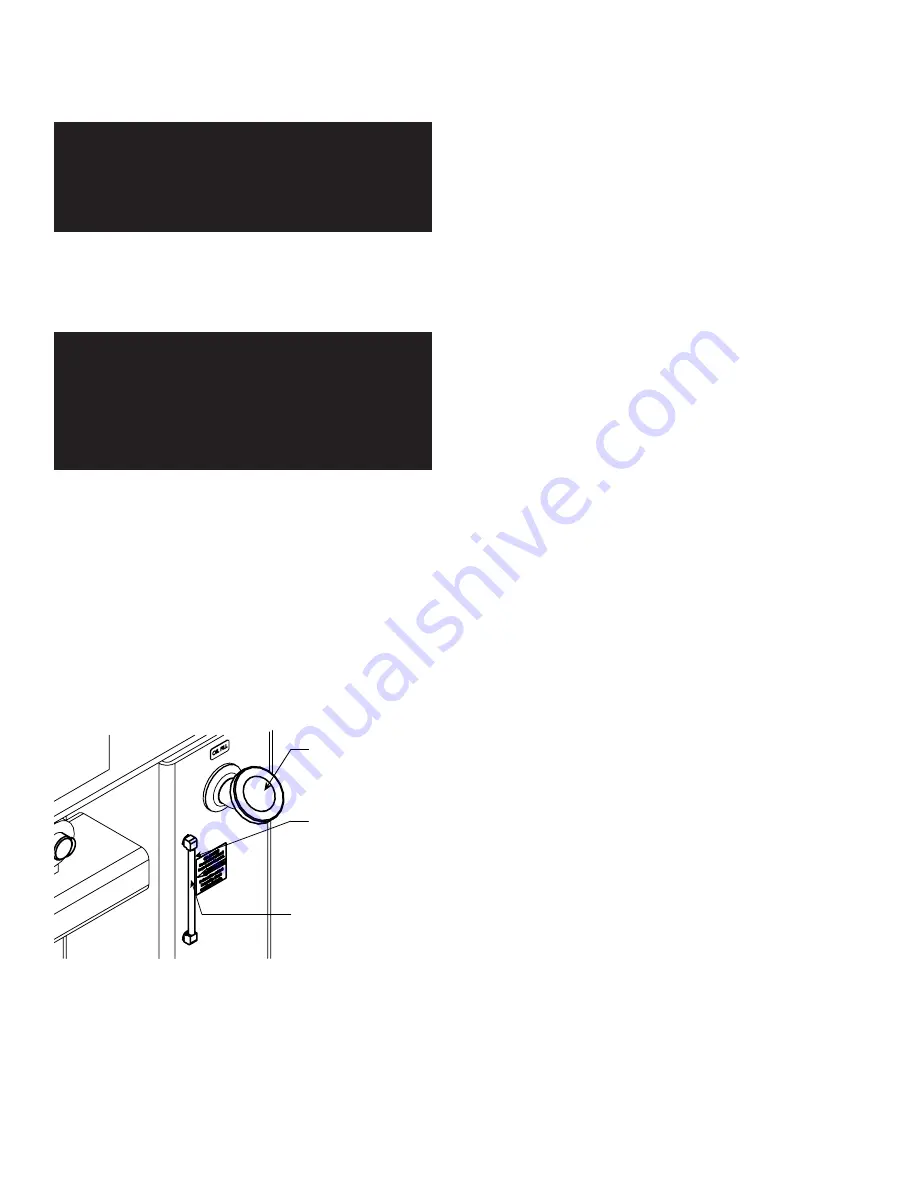
Do not allow Oil
to fall below
this point.
Sight Gauge
Breather Cap,
remove to add Oil.
5. Plug the Power Cord into the receptacle closest to the
available circuit panel.
6. Turn the Power Switch on, then operate the
Directional Control Valves and allow the Cylinders to
move in and out a number of times.
8 Bender Operation Manual
Summary of Contents for BB 1302-BA
Page 50: ...50 Bender Operation Manual...
Page 51: ...Bender Operation Manual 51...
Page 56: ...56 Bender Operation Manual...
Page 57: ...Bender Operation Manual 57...
Page 58: ...58 Bender Operation Manual...
Page 59: ...Bender Operation Manual 59...
Page 60: ...60 Bender Operation Manual...
Page 61: ...Bender Operation Manual 61...
Page 62: ...62 Bender Operation Manual...
Page 63: ...Bender Operation Manual 63...
Page 64: ...64 Bender Operation Manual...
Page 65: ...Bender Operation Manual 65...


