7. Visually check bronze bushings for excessive wear.
Replace bushings if inside diameter is greater than
2.005” or more.
(See figure 3-A)
8. After check is completed, reverse steps and adjust
chain assembly as described on page 34.
IMPORTANT NOTE:
Be sure to Grease the Zirk Fittings on each side of the
barrel after re-installation of Gate Assemblies.
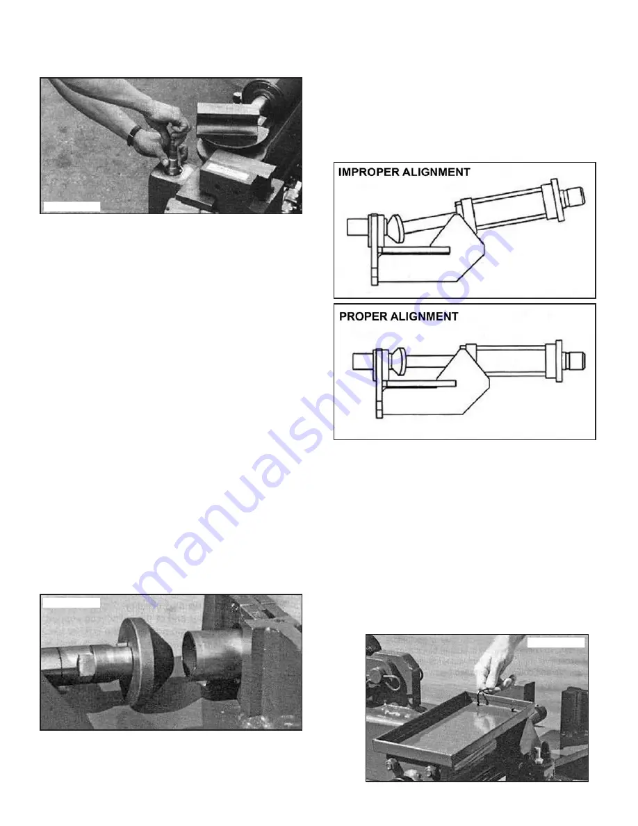
ALIGNING THE SWAGING
BOX CYLINDER
The Swaging Cylinder should be checked periodically for
proper alignment. If the Swaging Cylinder is not square
or centered with the swaging Clamp Blocks, the Tubing
will not expand correctly.
NOTE:
If the Swaging Cylinder is damaged or bent due to
improper use, there is no way to correct this, other than
total replacement of the cylinder.
To properly check the Swaging Cylinder for proper
alignment, follow the steps outlined below:
1. Turn the machine on.
2. Install a HPF-300 or similar Tool on the ST-1 Adapter.
(See figure 3-B)
3. Position a section of squarely cut 2” Tubing
approximately 12” long into the clamp block area
using the necessary HAC Adapter Collar.
4. Gently snug the Collar back into the Clamp Blocks by
gently pushing back on the Collar Assembly.
5. Hold the Tubing securely making sure that the
HAC-300 is square within the Clamp Blocks.
6. Advance the Tool forward until it just makes contact
with the Tubing.
7. At this time, the Tool should contact the complete
circumference of the Tubing end simultaneously. If
the Swaging Cylinder is out of alignment or the Cylinder
shaft is bent, then the Tool will only partially contact
the Tubing circumference. (See illustrations)
8. If the Swaging Cylinder is out of alignment, proceed
as follows to make proper adjustments:
9. Turn the machine off until all necessary adjustments
are made.
10. Remove the two allen bolts securing the Swaging
Tool tray using a 1/8” Hex Wrench. (See figure 3-C)
11. Loosen the four (4) 1/2” nuts (or bolts) attaching the
cylinder to the Swaging box using a 3/4” socket or
Open-End Wrench. It is not necessary to completely
remove the Nuts or Bolts. (See figure 1-A)
Figure 3-A
Figure 3-B
Figure 3-C
38 Bender Operation Manual
Summary of Contents for BB 1302-BA
Page 50: ...50 Bender Operation Manual...
Page 51: ...Bender Operation Manual 51...
Page 56: ...56 Bender Operation Manual...
Page 57: ...Bender Operation Manual 57...
Page 58: ...58 Bender Operation Manual...
Page 59: ...Bender Operation Manual 59...
Page 60: ...60 Bender Operation Manual...
Page 61: ...Bender Operation Manual 61...
Page 62: ...62 Bender Operation Manual...
Page 63: ...Bender Operation Manual 63...
Page 64: ...64 Bender Operation Manual...
Page 65: ...Bender Operation Manual 65...


