GUIDE TO INSTALLATION AND OPERATION
26
| HCO-3901
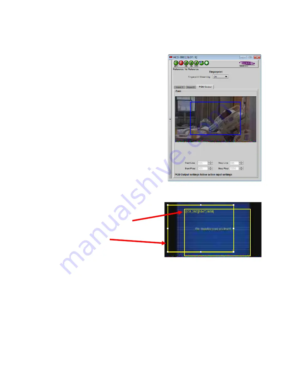
Note: The windows for Inputs 1 and 2 can be adjusted independently. The PGM Output window settings follow those
of the selected input, and are shown in the tab but cannot be adjusted there.
Zone
Select the area of the image within which fingerprint data will be
calculated and streamed.
•
The selected area is shown as a blue outline on the control
panel window, superimposed over a thumbnail of the video.
•
The thumbnail is only available when the Input Control box is
selected in the Thumbnail panel.
Default Window
– a factory default is specified which is applied
consistently to all Grass Valley fingerprinting devices. It places the
window in the central “action area” of the image, generally avoiding
letterboxes and static graphics that are usually found in the periphery
of the image.
Full Screen
– opens the window to include the complete video image.
Start/Stop Line & Pixel
– allows the user to create a custom window in
response to particular or unusual image content.
•
The custom window can be placed anywhere within the picture.
•
Type the value into the data box and Enter, or use the scroll
arrows to change the value
Use a mouse to resize
– you may also use your mouse to move and
resize the window. Click within the blue frame and it will turn yellow
and display control handles. Mouse over a handle until the cursor
switches to an arrow icon, and then drag the handle to resize the
window. When you are not over a handle, the 4-arrow cursor allows you to drag the window to a new location
•
While you are resizing with the mouse, the start and stop line
and pixel are shown in the top left of the frame area, in this
format:
[start line, start pixel][stop line, stop pixel]
•
The original position of the frame remains visible, so the
amount of change can easily be seen
In operation:
•
Use the fingerprints from Inputs 1 and 2 for comparison with fingerprints from upstream sources
•
Use the fingerprint from the output for comparison with fingerprints from downstream devices.
Figure 3.27 Fingerprint panel – PGM output


