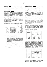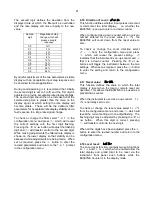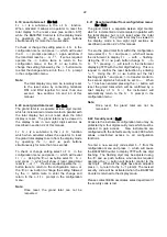
not required when the Counter input is connected to
a voltage pulse source.
Fitting an external link between terminals 3 & 4
changes the Counter's pulse input safety parameters
in normal operation as shown below. This table also
shows the types of sensor requiring energising (link
fitting).
Safety parameters
Input
Output
Type of input Link 3 & 4 Ui
Uo
Io
Switch contact
Yes
15V
10.5V 9.2mA
Proximity detector
Yes
15V
10.5V 9.2mA
Open collector
Yes
15V
10.5V 9.2mA
Magnetic pick-off
No
30V
1.1V
0.5mA
Voltage input (low)
No
30V
1.1V
0.5mA
Voltage input (high)
No
30V
1.1V
0.5mA
3.6 Remote reset terminals
The BA367NE total display my be reset to zero by
connecting the external reset terminals RS1 and
RS2 together for more than one second. The two
reset terminals have the following safety parameters
in normal operation:
Ui
=
30V
Uo
=
3.8V
Io
=
1mA
3.7 Certification label information
The Counter certification information label is fitted in
a recess on the top outer surface of the enclosure. It
shows the ATEX and IECEx certification information
plus BEKA associates name, location, year of
manufacture and the instrument serial number.
BA367NE Certification information label
4. SYSTEM DESIGN FOR HAZARDOUS AREAS
When correctly installed in Zone 2 the BA367NE
Counter may be connected to almost any apparatus
in the safe area and to Ex n, Ex e, Ex p and Ex d
protected apparatus located in Zone 2. Because
the BA367NE is not certified intrinsically safe it
should not be connected to an intrinsically safe
system.
BEKA Application Guide AG310,
Guide for
Installation of [extra low voltage d.c.] Ex nA
instrumentation
, which can be downloaded from
www.beka.co.uk, contains explanations and
recommendations for the installation of Ex nA
equipment.
In addition to being able to be connected to other
equipment in the safe area and in Zone 2, the
BA367NE may also be connected to suitably
protected and certified equipment located in Zone 1.
This is illustrated in Fig 5 and explained in
Application Guide AG310.
There are four design requirements:
1. The BA367NE must be installed in a panel
enclosure complying with the requirements for
Ex n protection as shown in section 5 of this
manual.
2. The BA367NE should be powered from a
circuit that has output safety parameters in
normal operation equal to, or less than, the
input safety parameters for terminals 1 and
2 specified by the BA337NG ATEX Type
Examination Certificate.
3. Hazardous area apparatus to which the
BA367NE is connected should be protected
by a technique suitable for the Zone in
which the equipment is located such as Ex n
or Ex e if located in Zone 2. Equipment
protected by intrinsic safety should not be
connected to a BA367NE.
4. Wiring should comply with Clause 9 of
EN 60079-14.
When designing a system it is important to
remember that terminals 2, 6 and RS2 are
interconnected within the BA367NE. See Fig 1.
7
Summary of Contents for BA364G
Page 1: ...Issue 7 9th July 2019 BA367NE One input Ex nA and Ex tc Counter Issue 7 ...
Page 16: ...16 ...
Page 17: ...17 ...


