


6.2 Accessing configuration functions
Throughout this manual the instrument front panel
push buttons are shown as
&
,
*
,
(
and
)
and
legends displayed by the instrument are shown in a
seven segment font as displayed by the Counter
e.g.
FiLtEr
and
5CALE
.
r
.
Access to the configuration menu is obtained by
operating the
(
and
)
push buttons
simultaneously. If the instrument is not protected by
a security code the first parameter
inPut
will be
displayed. If a security code other than the default
code
0000
has already been entered, the instrument
will display
CodE
. Press
(
to clear this prompt and
enter the security code for the instrument using the
&
or
*
push button to adjust the flashing digit,
and the
(
push button to transfer control to the
next digit. If the correct code has been entered
pressing
)
will cause the first parameter
inPut
to
be displayed. If an incorrect code is entered, or a
push button is not operated within ten seconds, the
instrument will automatically return to the display
mode.
All configuration functions and prompts are shown
on the upper eight digit display.
Once within the configuration menu the required
function can be selected by scrolling through the
menu using the
&
and
*
push buttons. The
configuration menu is shown diagrammatically in
Fig 11.
When returning to the display mode following
reconfiguration, the BA367NE Counter will display
dAtA
followed by
5AVE
while the new information is
stored in permanent memory.
If after accessing the configuration menu the interval
between operating any front panel push button
exceeds one minute, the BA367NE will automatically
return to the display mode and any configuration
changes will not be stored in permanent memory.
When making changes to multiple configuration
functions, it is therefore sensible to occasionally
return to the display mode to save the changes that
have already been made.
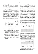
6.3 Summary of configuration functions
This section summarises all the configuration
functions. When read in conjunction with Fig 11 it
provides a quick aid for configuring the Counter. If
more detail is required, each section contains a
reference to a full description of the function.
Display Summary of function
inPut
Input
Contains sub-menu with two
functions:
inP . tYPE
Select Input type
dEbounCE
Set debounce
See section 6.4
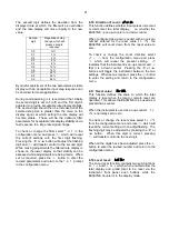
inP
.
tYPE
Configures input to accept one of six
types of input:
oP
.
CoL
Open collector
*
VoLt5 L
Voltage pulse <1 >3V
VoLt5 H
Voltage pulse <3 >10V
CoiL
Magnetic pick-off
Pr
.
dEt
Proximity detector
*
ContACt
Switch contact
*
*
Link terminals 3 & 4
See section 6.5
dEbounCE
[[
Defines
level of input debounce
applied to the pulse input to prevent
false counting:
dEFAuLt
HEAVY
LiGHt
See section 6.6
Cnt EdGE
Input pulse counting edge
Defines whether the Counter is
incremented/decremented on the
leading or trailing edge of an input
pulse.
See section 6.7
updAtE
Display update interval
Defines the interval between display
updates between 0.5 and 5
seconds.
See section 6.8
13
Summary of Contents for BA364G
Page 1: ...Issue 7 9th July 2019 BA367NE One input Ex nA and Ex tc Counter Issue 7 ...
Page 16: ...16 ...
Page 17: ...17 ...