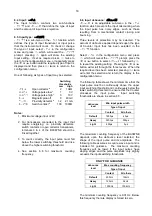
Step 3
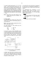
Select display update
To aid reading the display the BA367NE
is only to be updated every 3 seconds.
Select
uPdAtE
from the configuration
menu and press
(
. Using the
&
or
*
button select
3
and press
)
to return to
the
uPdAtE
prompt in the configuration
menu.
Step 4
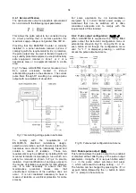
Define function of upper display
In the example the total number of
strokes is required on the larger eight
digit upper display.
Select
dI5P-1
from the configuration
menu and press
(
which will reveal if
the upper display is showing
rAtE
or
totAL
. Using the
&
or
*
button select
totAL
followed by the
)
button to enter
the selection and return to the
configuration menu.
Step 5
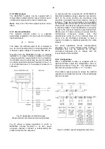
Activate lower rate display
A rate display is required so the lower
display must be activated.
Select
di5PLAY.2
from the main menu
and press
(
to show the existing
setting. Using the
&
or
*
button
select
on
followed by
)
to enter the
selection and return to the configuration
menu.
Step 6
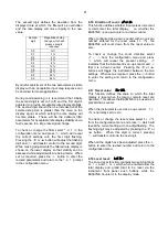
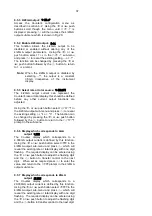
Position of decimal point
In this example the BA367NE is required
to display total and rate with no decimal
points.
Select
d.P.
from the configuration menu
and press
(
. The BA367NE will show
and identify the total display with all the
digits activated. Using the
&
or
*
button position the decimal point to the
right of the least significant digit i.e. not
visible.
Operating the
(
button will show and
identify the rate display with all the digits
activated, Again using the
&
or
*
button position the decimal point to the
right of the least significant digit i.e. not
visible.
Finally press
)
to return to the
configuration menu.
Step 7
Enter the total scale factor
In this example the proximity detector
produce four pulses per pump stroke.
The BA367NE is required to display
thousands of pump strokes therefore the
total scale factor
5CALE.t
should be set to
(4 x 1000) = 4000.
Select
5CALE.t
from the configuration
menu and press
(
to view the current
value with one digit flashing. Use the
&
or
*
button to adjust the flashing
digit and the
(
button to transfer control
to the next digit and to the decimal point.
Enter
4000.0
and return to the
5CALE.t
prompt in the configuration menu by
pressing
)
.
Step 8
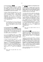
Enter the rate scale factor
The proximity detector produces four
pulses per pump stroke and the rate
display is required in strokes per hour,
therefore the rate scale factor
5CALE.r
should be set to 4.0.
Select
5CALE.r
from the configuration
menu and press
(
to view the current
value with one digit flashing. Use the
&
or
*
button to adjust the flashing digit
and the
(
button to transfer control to
the next digit and to the decimal point.
Enter
4.0
and return to the
5CALE.r
prompt
in the configuration menu by pressing
)
.
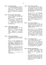
Step 9
Set the display timebase
In this example the rate display is
required in pump strokes per hour.
Select
t-bA5E
from the configuration
menu and press
(
to reveal the current
setting. Using the
&
or
*
button scroll
through the three options and select
tb-3600
. Return to the
t-bASE
prompt in
the configuration menu by pressing
)
.
Step 10 Adjust the rate display filter
The rate display filter parameters should
be adjusted experimentally after
installation to provide a stable rate
display with an acceptable step
response.
During commissioning it is recommend
that initially the second digit of the rate
parameters is set to 0 (step response off)
and the first digit (amount of filtering) is
adjusted to provide acceptable rate
display stability.
24
Summary of Contents for BA364G
Page 1: ...Issue 7 9th July 2019 BA367NE One input Ex nA and Ex tc Counter Issue 7 ...
Page 16: ...16 ...
Page 17: ...17 ...


