9.4.1 Ex nA certification
The optional pulse output is a separate opto-isolated
Ex nA circuit with the following input parameters:
Ui
=
30V dc
Ii
=
100mA
This allows the pulse output to be connected to any
dc circuit providing that in normal operation the
maximum supply voltage is not greater than 30V dc.
Providing that the BA367NE Counter is correctly
installed in a panel enclosure located in Zone 2
complying with the requirements for Ex n protection,
the pulse output may be used to transmit a pulse to
any suitably protected equipment, except intrinsically
safe equipment, located in Zone 1 or 2 of a
hazardous area, or to equipment located in a safe
area.
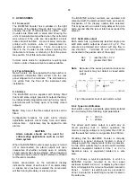
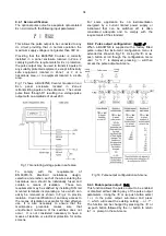
Fig 17 shows a BA367NE Counter mounted in an
Ex
n panel enclosure located in Zone
2
retransmitting a pulse to the safe area. The current
pulse flows through R1 resulting in a voltage pulse
output with an amplitude of about 20V.
Fig 17 Generating voltage pulse in safe area
To comply with the requirements of
EN 60079-14
Electrical installations design,
selection and erection
, each of the wires entering the
hazardous area should be individually fused and
contain a means of isolation. These two
requirements may be satisfied by installing DIN rail
mounted terminals incorporating a fuse which can
easily be removed as shown in Fig 2 to provide
isolation. Clear identification of, and easy access to
the means of isolation is essential for their effective
use. It is also necessary to ensure that the
maintenance procedure makes sure that
unauthorised re-closure of the switches does not
occur. It is not considered necessary to have a
means of isolation or electrical protection for cable
screens.
For some application Ex nA instrumentation
energised by a current limited power supply or
instrument that can be switched off, is often
considered adequate and to comply with the
requirements of the standard.
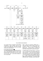
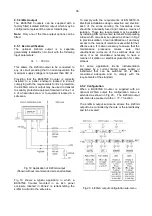
9.4.2 Pulse output configuration:
PuL5E oP
When a BA367NE is supplied with a factory fitted
pulse output the instrument configuration menu is
extended as shown in Fig 18. Using the
&
or
*
push button scroll though the configuration menu
until
PuL5E
oP
is displayed, pressing
(
will then
access the pulse output sub-menu.
Fig 18 Pulse output configuration sub-menu
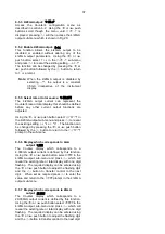
9.4.3 Enable pulse output:
EnbL
This function allows the pulse output to be enabled
or disabled without altering any of the pulse output
parameters. Using the
&
or
*
push button select
EnbL
in the pulse output sub-menu and press
(
which will reveal the existing setting
on
or
oFF
.
The function can be changed by pressing the
&
or
*
push button followed by the
)
button to return
to
EnbL
prompt in the sub-menu.
34
Summary of Contents for BA364G
Page 1: ...Issue 7 9th July 2019 BA367NE One input Ex nA and Ex tc Counter Issue 7 ...
Page 16: ...16 ...
Page 17: ...17 ...


