© 2012, Japan Cash
M
achine Co., Limited
Support:
http://www.jcmglobal.com/en/contact/default.aspx
Web-Site:
http://www.jcmglobal.com
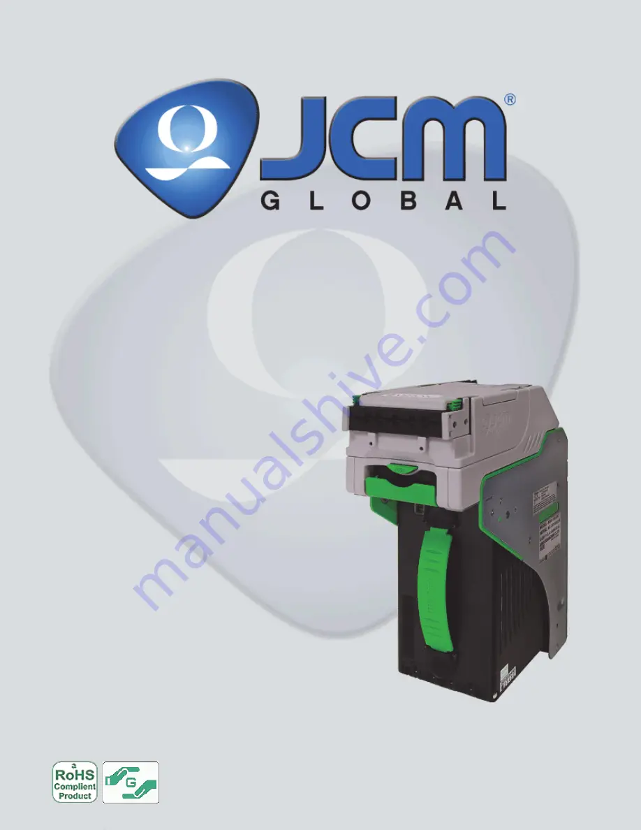
iVIZION
®
Series
Next-Generation Banknote
Acceptor Unit
Operation and Maintenance
Manual
(Revision 3)
P/N 960-100929R_Rev. 3 {EDP #148849}
Issue #4074-SME-01-03


