


Commissioning
EL3773
142
Version: 2.5
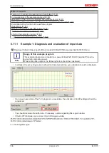
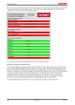
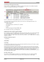
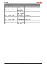
Errors that have occurred are displayed on the second page of the visualization (see fig.
Second page of the
visualization of the EL3773 example program
). In this case, for example, the EtherCAT cable from the
controller to the coupler was removed during operation.
Fig. 158: Second page of the visualization of the EL3773 example program
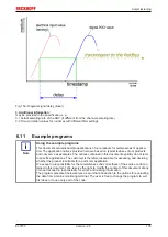
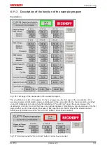
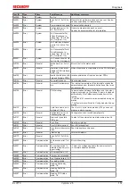
Selection of the size of the FIFO buffer
The recorded samples are copied per cycle into a FIFO buffer in which the newest values are saved "at the
front" and the oldest values are discarded "at the rear". The size of the FIFO buffer can be specified at the
beginning and should be selected according to the oversampling factor, the cycle time and the connected
frequency. Important for an accurate evaluation of the connected voltages and currents is a sufficiently large
memory of recorded values. If the connected frequency is, for example, 50 Hz, then 4 values will be
recorded per PLC cycle with an oversampling factor of 20 and a cycle time of 5 ms. The period at a
frequency of 50 Hz is 20 ms and with the selected settings an entire period is sampled with 80 values.
Hence, the size of the FIFO buffer should be an integral multiple of 80, for example 800.
The following illustration provides an overview of the principle of operation of the data buffer:
Summary of Contents for EL3773
Page 1: ...Documentation EL3773 Power Monitoring Oversampling Terminal 2 5 2018 03 13 Version Date...
Page 2: ......
Page 6: ...Table of contents EL3773 6 Version 2 5...
Page 39: ...Mounting and wiring EL3773 39 Version 2 5 Fig 29 Other installation positions...
Page 41: ...Mounting and wiring EL3773 41 Version 2 5 Fig 31 Block diagram...
Page 47: ...Commissioning EL3773 47 Version 2 5 Fig 38 Incorrect driver settings for the Ethernet port...
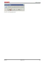
Page 147: ...Commissioning EL3773 147 Version 2 5 Fig 168 Confirming program start...


