


Commissioning
EL3773
138
Version: 2.5
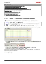
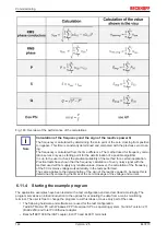
◦ RMS voltage of the external conductors
◦ Apparent, active and reactive power for each channel and in total
◦ Power factor (cos φ) for each phase
◦ Frequency of each voltage channel
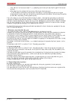
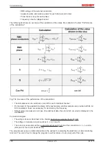
The following list shows an overview of the calculation of the values. More details in the item "Performance
of the calculations"
Fig. 154: Overview of the performance of the calculations
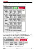
• The calculations can be switched on and off for each individual channel
• On the basis of the supplied time stamp of the next sample, all other samples are provided with 64 bit
DC time stamps; these are necessary for determining the frequency
• Default values are passed on in case of invalid input data; the error which occurred is displayed in the
visualization
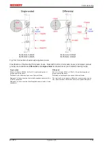
Connection diagram:
• The wiring is done as described in the chapter
• The voltage is measured via connections L1, L2, L3 and N.
• The current is measured via three
and the connections I
L1
, I
L2
, I
L3
and I
N
(star point of the current transformers).
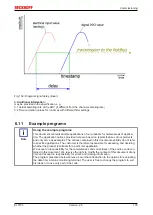
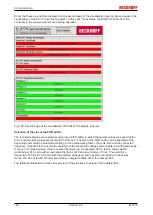
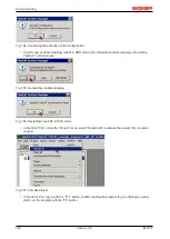
The program serves as an initial introduction to the options for evaluating the data from a mains monitoring
terminal. The user is free to change the program to suit his ideas or to use only part of the code.
Summary of Contents for EL3773
Page 1: ...Documentation EL3773 Power Monitoring Oversampling Terminal 2 5 2018 03 13 Version Date...
Page 2: ......
Page 6: ...Table of contents EL3773 6 Version 2 5...
Page 39: ...Mounting and wiring EL3773 39 Version 2 5 Fig 29 Other installation positions...
Page 41: ...Mounting and wiring EL3773 41 Version 2 5 Fig 31 Block diagram...
Page 47: ...Commissioning EL3773 47 Version 2 5 Fig 38 Incorrect driver settings for the Ethernet port...
Page 147: ...Commissioning EL3773 147 Version 2 5 Fig 168 Confirming program start...


