Operating Instructions WSTE 500 and WSTE 1000
25
E
N
G
L
I
S
H
6. Button input - UP / STOP / UP inside
A pull switch or keyswitch can be connected to terminals A6/B6 (WSTE 500) and to terminals A10/B10 (WSTE
1000). The function is UP when the door is closed, STOP when the door is moving and UP again when the door is
half-open.
The DOWN function is only executed via the pull switch when the door is in the upper final position.
If the traffic light control (two-way traffic control) is used, the traffic light is switched to green inside the underground
garage by the UP command via terminals A10/B10. The control recognises the command as “UP from inside”.
Accordingly, the traffic light allows exit from the underground garage.
7. Button input UP / STOP / UP outside (in the case of WSTE 1000)
A pull switch or keyswitch can also be connected to terminals A11 and B11. The function is identical to point 6.
In this case, if the traffic light control (two-way traffic control) is used, the traffic light outside the underground garage
is switched to green by the UP command via terminals A11/B11. The control recognises the command as “UP from
outside”. Accordingly, the traffic light allows entry into the underground garage.
8. Reclosing release
By connecting the terminals A7/B7 (WSTE 500) and terminals A9/B9 (WSTE 1000) (e.g. with a jumper) the “Auto-
matic reclosing” function is activated. The reclosing delay is set with the potentiometer on the keyboard (inside of
cover) (setting range 8 - 200 seconds).
If the reclosing is only to be active at particular times, an external industrial programme timer with potential-free
contact must be connected.
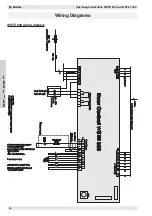
9. Roll-up safety device (roller grid) only in the case of WSTE 1000 (see WSTE 1000 wiring diagram)
A roll-up safety device (e.g. light barrier, steel cable or safety contact edge) can be connected to terminals A6 and
B6. This function is effective in the UP direction and performs a STOP function when activated. After activation of the
roll-up safety device, the automatic reclosing function is switched off, until a new command is given via the UP or
DOWN command transmitters.
In cases where the roll-up safety device is used in the EMERGENCY STOP safety circuit, if this
safety function activates, DOWN movement of the door can only be performed using the emergency
control “light hand-chain” or the emergency hand crank.
10. Light barrier (close to the floor)
A light barrier (installed approx. 30 - 50 cm above the floor) can be connected to terminals A7 / B7 (WSTE 1000).
This control input has two functions:
•
If the light beam from the light barrier is interrupted while the door is closing, the system stops and moves
into the upper final position after a short interval.
•
If the light beam from the light barrier is interrupted when the reclosing function is switched on and the door
is open (e.g. if a vehicle exits), the automatic closing time is reset to 8 seconds (clearing phase). The door
closes when this time has expired.
11. UP switch (door outside) - only WSTE 1000
To open the door from outside, a switch or induction loop or similar can be connected to terminals A9 / B9. If the
traffic light control (two-way traffic control) is used, this UP command switches the traffic light outside the under-
ground garage to green. The control recognises the command as “Up from outside”. Accordingly, the traffic light
allows entry into the underground garage. For the STOP and DOWN switching commands, use inputs A4, A5 and
B5 as described under point 5.
Integrated control elements
1. Door UP
If the UP button (on the front) is pressed, the door opens in self-latching mode. When it reaches the upper final
position or if a safety function for the UP direction actuates (e.g. roll-up safety device), the door stops automatically.
If the UP button is pressed, while the door is moving downwards, the door stops and moves up again after a short
interval.
2. STOP
The opening or closing door can be stopped in any position by pressing the STOP button (on the front).
3. Door DOWN
If the DOWN button (on the front) is pressed, the door closes. When it reaches the lower final position or if a safety
function for the DOWN direction actuates (e.g. wicket door contact) the door stops automatically.
If the bottom pneumatic safety edge or the light barrier actuates, the door stops and then moves into the upper final
position.
If the WSTE 500 or WSTE 1000 is equipped with a pneumatic safety edge, it is monitored by the “pressure testing”.
In the event of negative testing (see also notes on pages 11 and 12 in this regard), when the door next closes, the
door movement is only performed in “dead man’s mode”. In order to change over to self-locking again, a positive
test must be performed, or a “RESET” by switching off the power supply.


