


Display and operation elements
Operation manual
b maXX
BM4100 (NWR)
Document no.: 5.04052.09
Baumüller Nürnberg GmbH
44
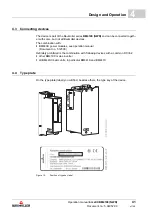
4.8
4.8
Display and operation elements
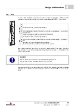
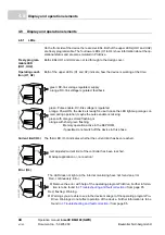
4.8.1
LEDs
On the front side of the device there are six LEDs. Both of the upper LEDs (UH1 and UH2)
are freely programmable. The four lower LEDs (H1 to H4) show information about the op-
erational status and are also emulated in ProDrive.
Freely program-
mable LED
(UH1, UH2)
Both LEDs UH1 and UH2 are not led through to the design cover.
Operating condi-
tion (H1, H2)
Both of the upper LEDs (H1 and H2) indicate, how the device is working at the time.
Current limit (H3)
The third LED (H-3) indicates whether the current limit has been reached.
Error (H4)
green: DC-link voltage regulated, supply
orange: DC-link voltage regulated, feedback
green: Pulse enable. DC-link voltage is regulated.
orange: Power ON, the device is ready-for-use. In case the LED lights up orange col-
ored during operation, maybe the pulse enable is missing.
green with orange-colored flashing or
orange with short green flashing:
Memory operation active in the EEPROM,
if possible do not switch off the device in this phase.
red: adjusted current limit of the controller has been reached.
h
Adapt application or „no reaction“.
The LED does not light up: the internal monitoring have not found an error.
Red, continuously: Error.
h
Remove the error with help of the operating program ProDrive. Further informa-
tion is to be found in
Troubleshooting and fault correction
Red, flashing: Warning.
h
Warnings you are able to see in the device manager of the operating program Pro-
Drive. Warnings do not affect operation of the device. Further information is to be
found in
Summary of Contents for b maXX 4100 Series
Page 143: ......


