


Installation
Operation manual
b maXX
BM4100 (NWR)
Document no.: 5.04052.09
69
7
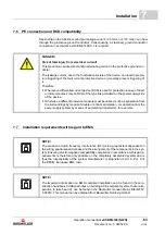
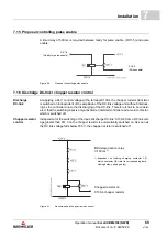
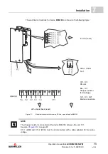
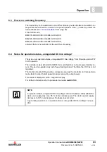
7.15 Proposal controlling pulse enable
A time delay of 500 ms is required between ready for pulse enable (D:X1-5) and pulse
enable.
Figure 26:
Proposal controlling pulse enable
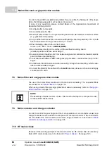
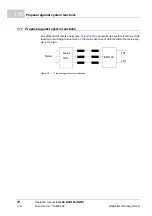
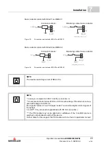
7.16 Discharge DC-link / chopper resistor control
Discharge
DC-link
At applying a 24 V control voltage at the terminal X100-4 the chopper resistor transistor
is switched on independent of the amplitude of the DC-link voltage and without interlock-
ing by the controller due to the discharging of the DC-link. Therefore it has to be consid-
ered, that the switching input is only activated at inhibited controller and a main contactor,
which is switched off.
Chopper resistor
control
Independent of the switching of the input „Discharge DC-link“ X100-4 from a DC link volt-
age greater than 814 V on the chopper resistor is automatically switched on. As soon as
the DC link voltage falls below 795 V, the chopper resistor is switched off.
Figure 27:
Recommended chopper resistor control
D:X1-5
(Ready for pulse enable)
F:X3-5
(Pulse enable)
BE delayed action relay
t=100 ms
1)
1)
dependent on loading charging contactor LS,
mains contactor HS (refer to corresponding data:
closing delay, opening delay)
Chopper resistor on
X100-4 chopper resistor
Summary of Contents for b maXX 4100 Series
Page 143: ......


