background image


Operating Manual for 

BAUER LINESTAR 9000 with hose feed 

35


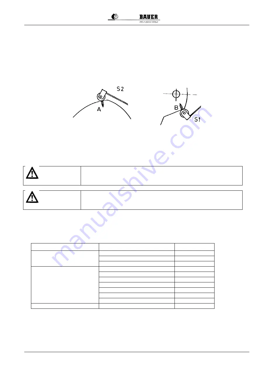
2.  Control switch: twist the switch cam until the switch roller touches notch „A“.  Move the switch in the bolt 

holes towards the switch cam until the control switch (

microswitch

) responds (

clicks

), the bracket of the 

switch lying next to the switch housing. Fix the switch with the screws in this position.  


3.  Safety switch: twist the control cam until the switch roller touches notch „B“. Move the switch toward the 

cam until it responds (

clicks

), the bracket of the switch lying next to the switch housing. Fix the switch with 

the screws in this position.  


4.  Check the switching points, repeat adjustment if necessary. 


A periodical check and re-adjustment (

if necessary

) of the exact switching points of the micro-switches is obligatory 

to guarantee a trouble-free operation of the machine. 
 

14 ELECTRICAL SYSTEM   


 WARNING ! 


System is powered by 230 Volts and 400 Volts (460 Volts) !  
All installation and service work must be performed with extreme care by 
an expert person - in strict compliance with the relevant safety codes !


 WARNING ! 


All electrical installation to be carried out ONLY after powering off the 
complete system!     


14.1 

CABLES AND MARKINGS 

 
1.  The pivot cable consists of 11 phases which are marked by colours. 


Phase colour 

Phase number 

Power circuit  

Black 

Blue 2 
Brown 3 

Control circuit 

Pink 

Grey 5 
Red 6 
White 7 
Violet 8 
Green 9 
Orange 10 

Grounding conductor 

yellow/green 


2. Cable 

lengths 

The cables are already cut to length and stripped at their ends at the manufacturer’s. Cables are long enough 
to enter the alignment controls in a slight loop.  
 

3.  Mounting the cables  

On the tower side of the span, where the alignment control has been mounted on the end pipe, the cable end is 

Summary of Contents for LINESTAR 9000

Page 1: ...OPERATING MANUAL for BAUER LINESTAR 9000 with hose feed Version XII 2013 850 9898 ...

Page 2: ...vailable at the time of printing BAUER reserves the right to change without notice without assuming any liability BAUER LINESTAR 9000 is designed for highest performance safety and reliability provided it is operated in accordance with the present operating instructions Therefore you should study this manual thoroughly before starting your BAUER LINESTAR 9000 Strictly observe all instructions pert...

Page 3: ...Manual for BAUER LINESTAR 9000 with hose feed III Owner of the machine This machine with the serial number Belongs to Name Address residence Telephone number Tutor Bauer dealer Service technician Telephone number ...

Page 4: ...customer or a nominated agent of the customer The customer confirms by signing that the machine has been test run before taken over A copy of the handing over record needs to be sent back to the company BAUER Ges m b H Comments For the customer For the company BAUER GMBH ______________________________ ______________________________ ...

Page 5: ...ation of span Spans fixed towable Booster pump yes no End gun yes no Equipment Linear control cable furrow induction Water supply ditch hose Feeding hose diam length Generator unit Comments Producer of the machine Röhren und Pumpenwerk BAUER Ges m b H Kowaldstrasse 2 A 8570 Voitsberg Tel 43 3142 200 0 Fax 43 3142 200 320 340 e mail sales bauer at com www bauer at com Dealer Name Address Tel Fax ...

Page 6: ...ENTRAL UNIT 14 9 CONTROL CENTRE 15 9 1 CONTROL CENTRE LINESTAR PRO 15 9 1 1 STANDARD BUILT IN COMPONENTS 16 9 2 CONTROL CENTRE LINESTAR PRO G 18 9 2 1 STANDARD BUILT IN COMPONENTS 19 10 LINEAR CONTROL SYSTEM 20 10 1 GENERAL 20 10 2 SPECIFIED MINIMUM CURVE RADIUS 21 10 3 FURROW GUIDANCE 22 10 4 CABLE GUIDANCE INSTALLATION AND ADJUSTMENT 22 10 5 BELOW GROUND GUIDANCE 24 10 5 1 OSCILLATOR BOX STEERIN...

Page 7: ...N OPERATING MODE WHEEL SWIVELLING 49 17 6 STARTING THE LINESTAR IN OPERATING MODE PIVOTING 49 17 7 SHUT DOWN PROCEDURE 50 17 7 1 LINESTAR SHUT DOWN DURING IRRIGATION 50 17 7 2 AUTOMATIC SHUT OFF OF LINESTAR 50 17 7 3 STARTING INTO OPPOSITE DIRECTION AFTER AUTOMATIC SHUT DOWN OF LINESTAR 51 18 MAINTENANCE INSTRUCTIONS 51 18 1 SERVICE INTERVALS 51 18 2 SERVICE PLAN 52 18 3 POST SEASON MAINTENANCE 54...

Page 8: ... 23 3 CONTROL CENTRE LINESTAR PRO G 81 23 3 1 CONTROL CENTRE LINESTAR PRO G WIRING DIAGRAM 1 81 23 3 2 CONTROL CENTRE LINESTAR PRO G INFEED 84 23 4 LINESTAR LINEAR CONTROL 86 23 4 1 FURROW GUIDANCE WIRING DIGRAM 87 23 4 2 CABLE GUIDANCE WIRING DIGRAM 88 23 4 3 BELOW GROUND GUIDANCE OSCILLATOR BOX WIRING DIGRAM 89 23 4 4 BELOW GROUND GUIDANCE TRACK UNIT WIRING DIGRAM 1 90 23 4 5 BELOW GROUND GUIDAN...

Page 9: ...lity law every farmer is an entrepreneur According to 9 PHG Product Liability Law liability for damage to corporeal things caused by defective products is expressly excluded This exclusion of liability also applies to parts not manufactured by BAUER itself but purchased from external suppliers Duty to furnish information Even if he passes on the machine to a new owner later on the customer is obli...

Page 10: ...power and read the operating manual 3 WARNING 1 This system is powered by 400 Volts Danger of electrical shock injury hazard 2 Do not attempt to check any components while the system is live 3 Open the inner pivot panel door only when main switch is OFF 4 WARNING 1 The working range of the pivot must always be at a safe distance from electrical power lines 2 Pull towable systems only at a safe dis...

Page 11: ...achine before every star 1 In addition to the instructions in this manual be sure to observe all specifications generally valid for safety and accident prevention 2 The warning signs and notes affixed to the machine contain information essential to safe operation Observing them serves your own personal safety 3 Do not start the machine unless all guards and safety devices are mounted completely an...

Page 12: ...bridge the system safety circuit except for system aligning by a qualified person 5 2 MECHANICAL SYSTEM WARNING 1 Never service or repair any part or system component while the machine is operating 2 Always disconnect the system from power before starting any maintenance work Turn the main switch to 0 and padlock the switch to prevent unintentional re closing Stop the generating unit Be sure to po...

Page 13: ... provides the electromechanical drive of the system Components wheel carrier tower bracing angle electrical drive motor drive shafts wheel gears and wheels TOWER COUPLING Joint between the spans Possible articulation up to 30 ALIGNMENT CONTROL Electromechanical control system that monitors the horizontal angular deviation between the spans and switches the drive motors OVERHANG Overhanging part fr...

Page 14: ... OF THE BELOW GROUND GUIDANCE 6 1 1 1 OSCILLATOR BOX ASSEMBLY OSCILLATOR BOX The oscillator box generates the signal required for the linear guidance which is fed to a conductor loop below ground cable COVER The cover serves to protect the unit against weather influences such as rain wind sun etc MOUNTING LEGS The oscillator box and cover are mounted to the two mounting legs Both mounting legs are...

Page 15: ...evices They receive the signal emitted by the underground cable 6 1 1 3 TRACK UNIT The signal received by the steering antenna is processed in the track unit and is transmitted to the control centre Auswerteeinheit Track Unit Antennenrohr Antenna Mounting Endstopp für LS m UG Strg End Stop Device f LS w BG Guidance Lenkantenne Steering Antenna ...

Page 16: ...al tower is located in the middle of the system and is part of the free standing span 6 2 2 END FEED The central tower is located at the end of the system being end tower as well Compared to the cable and furrow guidance the components of the Below Ground Guidance are always located in the centre of the machine ...

Page 17: ...ION The maximum permissible inclination along the travel direction in linear mode for the central tower as well as for the drive towers is 3 0 7 1 2 PERMISSIBLE BENDING ANGLES Maximum permissible inclination along the span is 3 0 Maximum difference in elevation between central tower and the first tower is 1 m ...

Page 18: ...ith hose feed 7 2 LIMITS WITH BELOW GROUND GUIDANCE 7 2 1 LIMITS WHEN USING AN OPEN CONDUCTOR LOOP OPEN CONDUCTOR LOOP symmetrical layout OPEN CONDUCTOR LOOP symmetrical layout 7 2 1 1 PERMISSIBLE BENDING ANGLES Steering antennas in middle of span ...

Page 19: ...MISSIBLE INCLINATION Steering antennas in middle of span 7 2 2 LIMITS WHEN USING AN OPEN CONDUCTOR LOOP WITH ASYMMETRICAL LAYOUT OPEN CONDUCTOR LOOP symmetrical layout In addition to the previously indicated limits the following deviation tolerances must be complied with ...

Page 20: ...m along the crop rows apply one of the following methods to determine the track Method I 1 Before cultivating make a dry run along the entire field to fix the tracks 2 Use these tracks as guidance for the crop row to be cultivated Keep a distance of 250 mm on both sides of the track for the first crop row Method II 1 Plant the entire field parallel to the system s travel direction 2 Make a dry run...

Page 21: ...er pipe DN 150 200 electrical shut off valve Control centre LINESTAR PRO LINESTAR PRO G Linear guidance furrow guidance cable guidance or below ground guidance Diesel power generator according to system requirements 10kVA 20kVA Supply hose according to system capacity 4 to 6 At the field end the supply hose must be connected to the rear side of the main cart for the return run Generatoraggregat Ge...

Page 22: ...shut off valve Control centre LINESTAR PRO LINESTAR PRO G Linear guidance furrow guidance cable guidance or below ground guidance Diesel power generator 8kVA 20kVA Connecting hose depending on system capacity 4 6 For towing the machine the wheels of the central tower can be swivelled electrically At the end of the field it is not necessary to change the connection of the supply hose at the central...

Page 23: ...operating panel can only be opened after turning off main switch Operating voltage 400 V Control voltage 230 V monophase Isolating transformer for control voltage Commercial contactors Wiring with lugs Protection devices ATTENTION To protect against soiling and splash water always close the control panel during operation 1 Main switch 2 Control panel LINESTAR PRO 3 Voltmeter 4 Switch LINESTAR OFF ...

Page 24: ... DISPLAY 2x16 alphanumeric LCD with backlight If no key is touched within a preset time the backlight turns off automatically adjustable backlight timer 9 1 1 2 2 FUNCTIONS MENU KEYS START FORWARD F Starts forward run clockwise START REVERSE R Starts reverse run anti clockwise MENU and ENTER By pressing this key you get access to user level it has got two more functions getting access to parameter...

Page 25: ...alignment Whenever the machine is running the switch must be in position ON in order to guarantee a safe unattended run 9 1 1 6 SWITCH END GUN OFF ON In position ON the end gun is in use in position OFF it is out of use 9 1 1 7 SWITCH GENERATOR OFF ON The generator unit shuts down automatically ON when system runs into safety circuit in case of pressure loss in supply line at end stop at intermedi...

Page 26: ... panel can only be opened after turning off main switch Operating voltage 400 V Control voltage 230 V monophase Isolating transformer for control voltage Commercial contactors Wiring with lugs Protection devices ATTENTION To protect against soiling and splash water always close the control panel during operation 1 Main switch 2 Control panel LINESTAR PRO G 3 Voltmeter 4 Switch LINESTAR OFF ON 5 Sw...

Page 27: ...1 DISPLAY 2x16 alphanumeric LCD with backlight If no key is touched within a preset time the backlight turns off automatically adjustable backlight timer 9 2 1 2 2 FUNCTIONS MENU KEYS START FORWARD F Starts forward run clockwise START REVERSE R Starts reverse run anti clockwise MENU and ENTER By pressing this key you get access to user level it has got two more functions getting access to paramete...

Page 28: ...down automatically for the above mentioned reasons This setting is used for aligning the LINESTAR dry run of LINESTAR 9 2 1 8 SWITCH EMERGENCY STOP Control unit is cut off power 10LINEAR CONTROL SYSTEM 10 1 GENERAL The LINESTAR is guided along a furrow in the ground FURROW GUIDANCE along a guiding cable CABLE GUIDANCE or contact free along a below ground cable BELOW GROUND GUIDANCE The linear cont...

Page 29: ...al for BAUER LINESTAR 9000 with hose feed 21 10 2 SPECIFIED MINIMUM CURVE RADIUS A end tower swivels around main cart Radius 2 x SL Radius min 600 m B main cart swivels around end tower Radius 3 x SL Radius min 900 m ...

Page 30: ...lation be sure to observe the following two conditions A The posts must be located in a perfectly straight line B The cable must be properly tensioned 2 Posts The posts must be paralleled to the ditch ditch feed or to the track of the central tower hose feed respectively They must be placed every 6 m in a straight line The last posts at the end of the field must be solidly embedded in the soil by ...

Page 31: ...nd of the cable attach a second 10 m long cable to the main cable with three clips Fasten the end of this second cable to a vehicle or a tractor and pull until the cable is well tensioned Recommended cable tension approx 4000 N After tensioning fasten the main cable to the end post and remove the auxiliary cable Klemme Clip Seil Cable Seilhalter Cable Holder Seilklemmen Cable Clamps 2 Seil Second ...

Page 32: ...eet cover and it is set up on the corresponding mounting legs directly on the field anywhere along the conductor loop It is purposeful not to set it up on the irrigated planted surface Steuereinheit Control Unit Steuerrolle Control Roller Steuerseil Control Cable Seilhalter Cable Holder Frequenzgenerator komplett Oscillator Box Assembly Frequenzgenerator Oscillator Box Abdeckung Cover Tragewinkel ...

Page 33: ...At first putting into operation the below ground cable will generally be connected to the long connection terminal of the oscillator box If the system works duly the green LED will be lit First putting into operation is exclusively carried out under the presence of a BAUER technician or of an authorized dealer and it must not be carried out by unqualified personnel Connection short is appropriate ...

Page 34: ...ennas electric coils are installed which are able to detect lines of electric flux in horizontal and vertical direction to the ground caused by the current passing the below ground conductor As can be seen from the above sketch the direction of the voltage induced in a spool changes only when the antenna moves from the left to the right side and vice versa of the below ground cable Subsequently th...

Page 35: ...e maximum cable deviation must not exceed 1 5 cm Be sure that there are no abrupt changes in direction such as buckles etc in the cable because they would cause increased stresses in the trusses and or in the system and they would hence lead to malfunction If you use an OPEN CONDUCTOR LOOP WITH ASYMMETRICAL LAYOUT for the track guide see 7 2 2 Limits when using an open conductor loop with ASYMMETR...

Page 36: ...points for furrow and cable guidance is basically the same Position the central unit in relation to the cable or the furrow in such a way that both control arms when they are in their operating condition rollers on the cable or in the furrow form a straight line with the fixed control frame of the central unit Loosen the fixing screw on the control rod which actuates the control cam of the control...

Page 37: ... control rod must be fixed exactly in the centre between the switching points Set the second linear control system the same way 10 6 2 BELOW GROUND GUIDANCE Before starting ensure that the antennas of the below ground guidance are properly mounted and adjusted In this regard also read 12 ALIGNMENT OF THE LINESTAR and 15 FIRST START UP 10 7 SETTING STOP SWITCH There are switches on the central towe...

Page 38: ...unctions Intermediate stop Stops the system for instance between two hydrants to allow changing the hose connection Adjust the stop levers for the end stops in such a way to make them surely actuate the end stop switch CABLE GUIDANCE ACTUATE END STOP ACTUATE INTERMEDIATE STOP FURCHENSTEUERUNG Schalteranordnung FURROW GUIDANCE switch arrangement BELOW GROUND GUIDANCE ...

Page 39: ...ine with electric start including battery Generator directly coupled to the engine Unit cover Unit control panel with following functions and indications Three Ampere indicators one per phase One voltmeter with phase converter Frequency indicator Operating hour meter Luminous indication of malfunction Failure indicator for oil pressure cooling water temperature battery charging fuel Warning siren ...

Page 40: ... hose feed 12 2 ALIGN SPANS 90 AT RIGHT ANGLE TO THE CENTRAL UNIT The imagined connection between the tower motors must be an exact straight line 12 3 ALIGNING THE CENTRAL UNIT TO THE LINEAR GUIDANCE BELOW GROUND GUIDANCE Zentraleinheit Central tower ...

Page 41: ... to the spans At the same time this straight line must overlap with the below ground cable seen from top Correctly mounted the antennas should be as shown on the below figure Factory setting of the antennas has been calibrated to a height of 3 m Mind above all the identical height of the antennas since it influences directly the linear guidance Untergrundkabel buried cable Linearführung Untergrund...

Page 42: ...stem off in case of a too heavy doglegging In addition to the microswitches an RC link is mounted which compensates voltage peaks to protect the switching devices The exact adjustment of the switching devices is absolutely necessary for the proper functioning of the machine Each alignment control leaves the manufacturer s in adjusted and tested condition Operating voltage 400 V control voltage 220...

Page 43: ...es is obligatory to guarantee a trouble free operation of the machine 14ELECTRICAL SYSTEM WARNING System is powered by 230 Volts and 400 Volts 460 Volts All installation and service work must be performed with extreme care by an expert person in strict compliance with the relevant safety codes WARNING All electrical installation to be carried out ONLY after powering off the complete system 14 1 CA...

Page 44: ...ECTION 1 Feed 3 cables into the alignment control a incoming feeder cable b forwarding of feeder cable c cable to the tower drive motor 2 Connections according to the enclosed wiring diagrams 4 Distinguish between different alignment control options NOTE Correct wiring of all alignment controls is essential If phases are muddled up the towers travel into different directions 5 Connect both couplin...

Page 45: ...BOXES AND DRIVE MOTORS 15 3 1 GEARBOXES Worm gear with 50 1 reduction ratio Model for stationary systems for towable systems with freely rotating hub Used oil quality SAE 85W 140 multigrade oil Oil quantity approx 3 8 litres up to bottom edge of filling hole oil expansion is compensated by expansion membranes TNT Gearbox TNT wheel gears have got two grease zerk fittings to lubricate the shifting d...

Page 46: ...f you have purchased a LINESTAR with Below Ground Guidance be sure that the oscillator box is supplied with voltage With a 230V AC supply put the main switch of power supply to position 1 With a 24V DC battery supply 2 x 12V DC check if the batteries are connected and sufficiently loaded Ensure that the BELOW GROUND CABLE for linear guidance of the system is properly connected to the oscillator bo...

Page 47: ...ive values of the antennas do not lie between 12 000 and 16 000 The green indicator light O K lights up if the signal and the loop are functioning properly 15 5 CONTROL CENTRE WARNING All work on the electrical control system is to be done by a qualified electrician All metal components of the system must be properly grounded with a yellow green protective conductor The protective conductor must b...

Page 48: ...ter mounting i e the assumed connecting line of all drive motors does not form a perfect straight line the system needs to be aligned as follows NOTE In order to prevent a mechanical overload of the truss align the Linestar step by step starting at the system end The assumed line connecting all tower motors with the middle of the central tower must be perfectly straight Start generator unit Turn m...

Page 49: ...ate the control cam clockwise up to the reversing switch point click of the control switch count the number of rotations of the nut or the turns with the wrench 3 Wind back the control cam by half of the counted nut or wrench turns to make the switch roller rest exactly in the middle between switching and reversing point of the control switch 4 Fix the adjustment nut with the lock nut on the threa...

Page 50: ...hreaded rod until the above requirement is fulfilled The next step is to check if the drive motor of the second tower is positioned in front of an assumed line connecting the drive motor of the third tower and the middle of the central tower If this is not the case correct the alignment control on the second tower Now check all the towers step by step as described under a and b Re adjust alignment...

Page 51: ... the normal position 2 Start the generator unit Move the main switch to position 1 Move the Safety circuit ON OFF switch to the position ON Move the LINESTAR OFF ON switch to ON On the LINESTAR PRO PRO G control panel Press the button ENTER Menu the cursor begins to blink Use the buttons to set the LINEAR mode Confirm with the ENTER button Leave the programming mode with the ESC button Press the F...

Page 52: ...R 9000 with hose feed 15 9 2 AUSRICHTEN DER MASCHINE MIT UNTERGRUNDSTEUERUNG Ist das Untergrundkabel der Untergrundsteuerung außerhalb des Regelfensters der Untergrundsteuerungs antenne dann ist der Sicherheitskreis der Anlage unterbrochen ...

Page 53: ...in You can now start up the LINESTAR as described above If you do not want to move the antenna support and would rather move the entire system toward the linear guidance then proceed as follows Go to the Machine Parameters Menu on the control panel of the LINESTAR PRO PRO G Increase the value in the safety circuit window under the menu item STEERING SAFETY CIRCUIT until this is large enough to cov...

Page 54: ...he REVERSE button to start up the LINESTAR in the anti clockwise reverse direction When you have finished the alignment of the machine set the value in the safety circuit window under the menu item STEERING SAFETY CIRCUIT back to the default value 16 TERMINOLOGY Forward Looking from the central tower to the system the LINESTAR moves to the right Reverse Looking from the central tower to the system...

Page 55: ...g Be extremely cautious with live parts The start up as described below is valid for a BAUER LINESTAR 9000 without optional equipment If the system has got any optional equipment see chapter options it has to be set properly and turned on before the start up If you have purchased a LINESTAR with Below Ground Guidance be sure that the oscillator box is supplied with voltage With a 230V AC supply pu...

Page 56: ...or unit must be turned off separately Water supply will be cut automatically by the shut off valve 17 3 2 AUTOMATIC SYSTEMM SHUT OFF AT FIELD END The switches of the central unit shut the LINESTAR automatically down when they are actuated by the end stoppers which have been placed at the end of the field If the switch GENSET OFF ON has been put to ON the generator unit shuts down automatically If ...

Page 57: ...e furrow guidance and affix them to the central tower Put switch GENSET OFF ON to OFF Start the generator unit Turn main switch to position 1 Put switch LINESTAR OFF ON to ON Control panel LINESTAR PRO PRO G Press ENTER MENU key the cursor starts blinking Select mode WHEEL SWIVELLING with keys Confirm with ENTER Press ESC to exit programming mode Detach fixing device of drive console at wheel carr...

Page 58: ...t mode Pivoting with keys Confirm with Enter Exit programming mode with ESC Press Forward or Reverse key depending on travel direction Change application rate with keys Put switch GENSET OFF ON to ON 17 7 SHUT DOWN PROCEDURE 17 7 1 LINESTAR SHUT DOWN DURING IRRIGATION Control panel LINESTAR PRO PRO G Press ESC Stop key If switch GENSET OFF ON has been put to ON the generator unit shuts down automa...

Page 59: ...d they must be confirmed in the service plan The service plan is considered as evidence for warranty claims The meaning of the service plan The service plan stipulates the time and kind of service In the evidence spaces we confirm the carrying out of the service which can be a condition for possible warranty claims We kindly ask you to understand that normal wear and tear as well as damages due to...

Page 60: ... sand trap X X Booster pump spinning of shaft between engine and pump check if pump rotor rotates freely if existing X Check end gun if existing X Tower box transmission device Check switch cam and adjust if necessary X Check shifting travel of micro switches X X Check function of micro switches operation switch and safety switch X Check all electric connections for contact X Check tightness of al...

Page 61: ...s on bearing covers and the vent hole of the expansion chamber are not clogged X Wheel gear Type TNT Lubricate shifting device X X Drive motor Make sure the drainage hole at bottom side of the motor is not clogged X Wheel gear drive motor check tightness of shaft sealing rings X X Lubricate freewheel hubs of towable wheel gears X Check screw connections of driveline couplers X Check if rubber pack...

Page 62: ...control centre and alignment controls for damages due to oxidation rodents and insects 2 Open sand trap gate valve and flush pipelines 3 Check tightness of flange seals and connecting hoses 4 Close sand trap gate valve 5 Tension cable for cable guidance and align pegs 6 Draw a new furrow for the furrow guidance 7 Place and align the pegs correctly for intermediate stop and end stop 8 Unwind supply...

Page 63: ... finishing unlubricated Bolts with standard metric thread DIN 13 dimension quality torque preload force Nm N M 8 8 8 25 5 16230 M 10 8 8 50 25791 M 12 8 8 87 3 37657 M 14 8 8 138 3 51681 M 16 8 8 210 8 71196 M 20 8 8 411 9 111305 M 24 8 8 711 160338 Bolts with standard UNC thread dimension quality torque preload force Nm N 1 4 S 12 5 10080 5 16 S 21 3 13954 1 2 S 92 7 38463 Bolts with standard UNF...

Page 64: ...tch turned off safety disconnect Q1 turned off fuses of fuse switch disconnector defective fuses F1 F2 F3 F4 defective safety circuit interrupted because system flex larger than maximum permissible bending angle no water pressure only with low pressure shut off option turn it on turn it on replace defective fuses replace defective fuses see Restart after doglegging check water supply readjust pres...

Page 65: ...re properly re aligned Check travel direction when spans start moving In case of wrong direction release key at once Press keys R or F to activate the tower alignment switches for manual alignment at tower concerns alignment control units with tower alignment switch Selecting the proper running direction ensures that only the outer misaligned towers start moving when the drive is turned on The wro...

Page 66: ... for BAUER LINESTAR 9000 with hose feed 20TECHNICAL DATA 20 1 DIMENSIONS OF BAUER LINESTAR 9000 2 WHEEL 20 2 DIMENSIONS OF BAUER LINESTAR 9000 4 WHEEL ONE SIDED 20 3 DIMENSIONS OF BAUER LINESTAR 9000 4 WHEEL DOUBLE SIDED ...

Page 67: ...infall 21 2 ELECTRIC SHUT OFF VALVE CENTRAL UNIT An electric shut off valve in the supply line of the central tower is closed automatically if the LINESTAR shuts down by malfunction 21 3 END GUN To increase the irrigated strip width or the system spraying range inside the swivelling area an end gun can be mounted at the end of the LINESTAR overhang It may spray along the whole irrigation strip or ...

Page 68: ...on the base plate of the alignment control It allows the forward or backward move of the tower without having to open the alignment control This device facilitates system alignment at first start up or after changing the operating site 21 8 RUNNING LIGHT Mounted on the end tower or on the central unit This light is shining as long as the LINESTAR is operating 21 9 END STOP If it is necessary to st...

Page 69: ... the LINESTAR with below ground guidance System should be towed along an even track if possible along a cart track width 7 m The track must be even and clear of ruts grooves and furrows If there are ruts in the lane they have to be levelled Towing of the system inside the field off road should be avoided If the system has to be towed inside the field the travelling track must be levelled first and...

Page 70: ...gear is provided with shifting lever disengage wheel gear Detach gear carrier Swivel gear carrier together with wheel The coupling parts with the rubber packages have to stay at the wheel gear If necessary lift wheel carrier with jack or tractors hydraulics Put the drive shaft with the coupling parts on shaft holder which is mounted onto the tower bracing angle Fasten wheel gear carrier with conne...

Page 71: ... TOWER WHEELS Gehen Sie ähnlich wie in 22 1 2 SCHWENKEN DER RÄDER AM FAHRTURM vor Loosen and push back the drive shaft cover at wheel gear Loosen driver pin on wheel hub If wheel gear is provided with shifting lever disengage wheel gear Detach gear carrier Swivel gear carrier together with wheel The coupling parts with the rubber packages have to stay at the wheel gear If necessary lift wheel carr...

Page 72: ...hed on the wheel carrier 22 3 TOWING THE LINESTAR AT A FREESTANDING SPAN 22 3 1 SWIVELLING CENTRAL TOWER WHEELS ACCORDING TO ITEM 17 5 22 3 2 SWIVELLING TOWER WHEELS Loosen and push back the drive shaft cover at wheel gear Loosen driver pin on wheel hub If wheel gear is provided with shifting lever disengage wheel gear Detach gear carrier stabilizing cable stabilizing cable steering unit ...

Page 73: ...h steering brace A turned by 90 Mount steering device B on all towers except for end tower overhang 22 3 3 BRACING THE END TOWER AND THE CENTRAL UNIT The end tower is braced to the span on the overhang side with 2 stabilizing cables A drawbar is attached to the wheel base The central unit is braced to the span with two stabilizing cables A drawbar is attached to the central unit stabilizing cable ...

Page 74: ...E LINESTAR PRO G WIRING DIAGRAM 1 CONTROL CENTRE LINESTAR PRO G WIRING DIAGRAM 2 CONTROL CENTRE LINESTAR PRO G WIRING DIAGRAM 3 23 3 2 CONTROL CENTRE LINESTAR PRO G INFEED CONTROL CENTRE LINESTAR PRO G CONTROL CONTROL CENTRE LINESTAR PRO G GPS GSM 23 4 LINESTAR LINEAR CONTROL 23 4 1 FURROW GUIDANCE WIRING DIAGRAM 23 4 2 CABLE GUIDANCE WIRING DIAGRAM 23 4 3 BELOW GROUND GUIDANCE OSCILLATOR BOX WIRI...

Page 75: ...Operating Manual for BAUER LINESTAR 9000 with hose feed 67 23 1 CONTROL CENTER LINESTAR PRO 23 1 1 CONTROL CENTER LINESTAR PRO WIRING DIAGRAM 1 ...

Page 76: ...68 Operating Manual for BAUER LINESTAR 9000 with hose feed CONTROL CENTER LINESTAR PRO WIRING DIAGRAM 2 ...

Page 77: ...Operating Manual for BAUER LINESTAR 9000 with hose feed 69 CONTROL CENTER LINESTAR PRO WIRING DIAGRAM 3 ...

Page 78: ...70 Operating Manual for BAUER LINESTAR 9000 with hose feed 23 1 2 CONTROL CENTRE LINESTAR PRO INFEED ...

Page 79: ...Operating Manual for BAUER LINESTAR 9000 with hose feed 71 CONTROL CENTER LINESTAR PRO CONTROL 1 CONTROL CENTER LINESTAR PRO CONTROL 2 ...

Page 80: ...72 Operating Manual for BAUER LINESTAR 9000 with hose feed 23 2 CONTROL CENTRE LINESTAR PRO WITH BELOW GROUND GUIDANCE ...

Page 81: ...perating Manual for BAUER LINESTAR 9000 with hose feed 73 23 2 1 CONTROL CENTRE LINESTAR PRO W BELOW GROUND GUIDANCE WIRING DIAGRAM 1 CONTROL CENTRE LINESTAR PRO W BELOW GROUND GUIDANCE WIRING DIAGRAM 2 ...

Page 82: ...74 Operating Manual for BAUER LINESTAR 9000 with hose feed ...

Page 83: ...Operating Manual for BAUER LINESTAR 9000 with hose feed 75 CONTROL CENTRE LINESTAR PRO W BELOW GROUND GUIDANCE WIRING DIAGRAM 3 ...

Page 84: ...76 Operating Manual for BAUER LINESTAR 9000 with hose feed 23 2 2 CONTROL CENTRE LINESTAR PRO W BELOW GROUND GUIDANCE INFEED ...

Page 85: ...Operating Manual for BAUER LINESTAR 9000 with hose feed 77 CONTROL CENTRE LINESTAR PRO W BELOW GROUND GUIDANCE CONTROL 1 ...

Page 86: ...78 Operating Manual for BAUER LINESTAR 9000 with hose feed CONTROL CENTRE LINESTAR PRO W BELOW GROUND GUIDANCE CONTROL 2 ...

Page 87: ...Operating Manual for BAUER LINESTAR 9000 with hose feed 79 CONTROL CENTRE LINESTAR PRO W BELOW GROUND GUIDANCE CONTROL 3 ...

Page 88: ...80 Operating Manual for BAUER LINESTAR 9000 with hose feed CONTROL CENTRE LINESTAR PRO W BELOW GROUND GUIDANCE CONTROL 4 ...

Page 89: ...Operating Manual for BAUER LINESTAR 9000 with hose feed 81 23 3 CONTROL CENTRE LINESTAR PRO G 23 3 1 CONTROL CENTRE LINESTAR PRO G WIRING DIAGRAM 1 ...

Page 90: ...82 Operating Manual for BAUER LINESTAR 9000 with hose feed CONTROL CENTRE LINESTAR PRO G WIRING DIAGRAM 2 ...

Page 91: ...Operating Manual for BAUER LINESTAR 9000 with hose feed 83 CONTROL CENTRE LINESTAR PRO G WIRING DIAGRAM 3 ...

Page 92: ...84 Operating Manual for BAUER LINESTAR 9000 with hose feed 23 3 2 CONTROL CENTRE LINESTAR PRO G INFEED ...

Page 93: ...Operating Manual for BAUER LINESTAR 9000 with hose feed 85 CONTROL CENTRE LINESTAR PRO G CONTROL CONTROL CENTRE LINESTAR PRO G CONTROL ...

Page 94: ...86 Operating Manual for BAUER LINESTAR 9000 with hose feed 23 4 LINESTAR LINEAR CONTROL ...

Page 95: ...Operating Manual for BAUER LINESTAR 9000 with hose feed 87 23 4 1 FURROW GUIDANCE WIRING DIGRAM ...

Page 96: ...88 Operating Manual for BAUER LINESTAR 9000 with hose feed 23 4 2 CABLE GUIDANCE WIRING DIGRAM ...

Page 97: ...Operating Manual for BAUER LINESTAR 9000 with hose feed 89 23 4 3 BELOW GROUND GUIDANCE OSCILLATOR BOX WIRING DIGRAM ...

Page 98: ...90 Operating Manual for BAUER LINESTAR 9000 with hose feed 23 4 4 BELOW GROUND GUIDANCE TRACK UNIT WIRING DIGRAM 1 ...

Page 99: ...Operating Manual for BAUER LINESTAR 9000 with hose feed 91 23 4 5 BELOW GROUND GUIDANCE TRACK UNIT WIRING DIGRAM 2 ...

Page 100: ...92 Operating Manual for BAUER LINESTAR 9000 with hose feed 23 5 LINESTAR TOWER BOX 23 5 1 TOWER BOX STANDARD 23 5 2 TOWER BOX WITH TOWER ALIGNMENT SWITCH ...

Page 101: ...Operating Manual for BAUER LINESTAR 9000 with hose feed 93 ...

Page 102: ...94 Operating Manual for BAUER LINESTAR 9000 with hose feed 23 5 3 TOWER BOX WITH END TOWER MONITORING ...

Page 103: ...Operating Manual for BAUER LINESTAR 9000 with hose feed 95 23 5 4 TOWER BOX WITH TOWER ALIGNMENT SWITCH END TOWER MONITORING ...

Page 104: ...96 Operating Manual for BAUER LINESTAR 9000 with hose feed 23 5 5 END TOWER BOX STANDARD ...

Page 105: ...Operating Manual for BAUER LINESTAR 9000 with hose feed 97 23 5 6 END TOWER BOX WITH TOWER ALIGNMENT SWITCH ...

Page 106: ...98 Operating Manual for BAUER LINESTAR 9000 with hose feed 23 5 7 END TOWER BOX WITH END STOP ...

Page 107: ...Operating Manual for BAUER LINESTAR 9000 with hose feed 99 23 5 8 END TOWER BOX WITH END STOP TOWER ALIGNMENT SWITCH ...

Page 108: ...100 Operating Manual for BAUER LINESTAR 9000 with hose feed 23 5 9 END TOWER BOX WITH END STOP AUTOREVERSE ...

Page 109: ...Operating Manual for BAUER LINESTAR 9000 with hose feed 101 23 5 10 END TOWER BOX WITH END STOP AUTOREVERSE ...

Page 110: ...102 Operating Manual for BAUER LINESTAR 9000 with hose feed 23 6 BOOSTER PUMP FOR END GUN ...

Page 111: ...aintenance Intermediate maintenance Intermediate maintenance Intermediate maintenance Intermediate maintenance Oil change Annual maintenance Accomplished service Yes No Date Operating hours Confirmed by Intermediate maintenance Intermediate maintenance Intermediate maintenance Intermediate maintenance Intermediate maintenance Intermediate maintenance Intermediate maintenance Intermediate maintenan...

Page 112: ... Intermediate maintenance Intermediate maintenance Intermediate maintenance Intermediate maintenance Oil change Annual maintenance Accomplished service Yes No Date Operating hours Confirmed by Intermediate maintenance Intermediate maintenance Intermediate maintenance Intermediate maintenance Intermediate maintenance Intermediate maintenance Intermediate maintenance Intermediate maintenance Interme...

Page 113: ... Intermediate maintenance Intermediate maintenance Intermediate maintenance Intermediate maintenance Oil change Annual maintenance Accomplished service Yes No Date Operating hours Confirmed by Intermediate maintenance Intermediate maintenance Intermediate maintenance Intermediate maintenance Intermediate maintenance Intermediate maintenance Intermediate maintenance Intermediate maintenance Interme...

Page 114: ... Intermediate maintenance Intermediate maintenance Intermediate maintenance Intermediate maintenance Oil change Annual maintenance Accomplished service Yes No Date Operating hours Confirmed by Intermediate maintenance Intermediate maintenance Intermediate maintenance Intermediate maintenance Intermediate maintenance Intermediate maintenance Intermediate maintenance Intermediate maintenance Interme...

Page 115: ... amended have been applied analogously DIN EN ISO 12100 1 Safety of machinery Basic concepts general principles for design Part 1 Basic terminology methodology DIN EN ISO 12100 2 Safety of machinery Basic concepts general principles for design Part 2 Technical principles DIN EN 60204 1 Safety of machinery Electrical equipment of machines Part 1 General requirements EN ISO 14121 1 Safety of machine...

Reviews: