background image

SubStation User Manual 


Page 7 

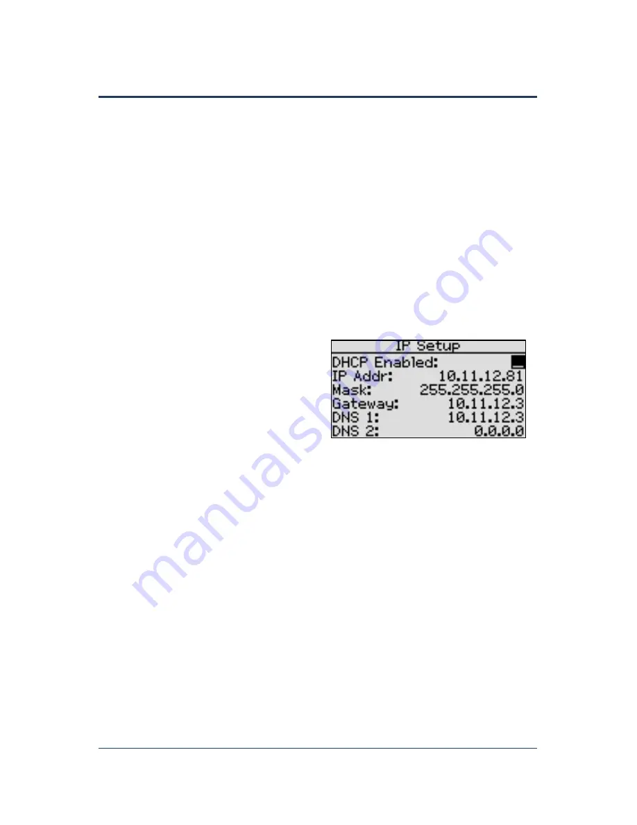
Setting Up a Static IP Address on the SubStation 

While DHCP (Dynamic Host Configuration Protocol) is the default network configuration for the 

SubStation, Baseline recommends that you set up a Static IP address in the SubStation. Giving the 

SubStation a Static IP address prevents you from having to reconfigure the connection between the 

SubStation and the BaseStation 3200 whenever the DHCP-assigned IP address changes on the 

SubStation.   

Ask your network administrator to set up a static IP address for the SubStation. Also ask your admin 

for the Subnet Mask, the Gateway, and the DNS settings for the network.   

1.


Make sure that the SubStation is connected to the network either with an Ethernet cable or a 

communication module. 

2.


On the controller, press the 

Setup 

button. The System Setup menu displays. 

3.


Press the 

 button to highlight the 

Network Setup

 option, and then press the 

OK

 button to 

select it. The Network Setup menu displays. 

4.


The 

IP Setup

 option should be highlighted. If it is not highlighted, press the 

 or 

 button to 

highlight it, and then press the 

OK

 button. The IP Setup screen displays. 

5.


Press the 

or

 –

 button to remove the 

checkmark in the 

DHCP Enabled

 field. The 

fields for the network settings display.   

Note

: For an explanation of the settings, 

refer to Viewing the IP Information Screen 

on page 87. 

6.


Determine the static IP address that you will 

assign to the SubStation. The IP address is based on the IP addresses of the other devices on 

the network, but 

it must have a unique last digit

.   

Example

: The SubStation and BaseStation 3200 are connected to a stand-alone network that 

does not have Internet access. The devices on this stand-alone network have IP addresses in 

the range 192.168.111.100 - 192.168.111.105. You can set the static IP address on the 

SubStation to 192.168.111.106. 

7.


Press the 

 button to highlight the first digits in the 

IP Addr 

field. 


Press the 

 or 

 button to move to the digits that you want to change. 


Press the 

or

 –

 button to change the value in the field. 

Note

: To rapidly increase or decrease the value, press and hold the 

+

 button or the 

 button. 

8.


Press the 

 button to move to the 

Mask

 field. Use the procedure described in step 7 to move 

within the digits and change the values. A typical value for the Subnet Mask is 255.255.255.0. 

9.


Press the 

 button to move to the 

Gateway

 field. Use the procedure described in step 7 to 

move within the digits and change the values.   

Example

: For the IP addresses in the example for step 6, the value for the Default Gateway 

would be 192.168.111.1. 

Summary of Contents for SubStation

Page 1: ...SubStation User Manual Firmware Version 2 0 February 5 2019 Customer Service 1 866 294 5847...

Page 2: ...Baseline Inc www baselinesystems com Phone 208 323 1634 FAX 208 323 1834 Toll Free 866 294 5847 2019 Baseline Inc All Rights Reserved...

Page 3: ...Setting the SubStation Date and Time 9 Setting Up the Screen Display 10 Clearing the Assigned Devices on the SubStation 10 Updating the Firmware on the SubStation 11 Exporting Data from the Controller...

Page 4: ...Page ii...

Page 5: ...ager The BaseStation 3200 has 8 available addresses for TCP IP based performance components Each SubStation connection uses one of these addresses The connections can be a combination of wired Etherne...

Page 6: ...ity in outdoor conditions including direct sunlight and low light Main Menu Buttons The buttons are used to select the various operating or programming menus of the SubStation An indicator light is il...

Page 7: ...IP Shows the Internet Protocol address IP address of the connected BaseStation 3200 irrigation controller Connect Time Shows the date and time when the connection between the SubStation and the BaseSt...

Page 8: ...ss the OK button The View Messages screen displays Note Messages notify you when something in your system needs your attention such as an open solenoid or no response from a device When your system is...

Page 9: ...he BACK button The Status Report menu displays 3 Press the or button to highlight System Status and then press the OK button The System Status screen displays Two wire voltage Two wire current The int...

Page 10: ...namic Host Configuration Protocol is the default network configuration for the SubStation DHCP allows the SubStation to automatically obtain an IP address which enables the connection to the network I...

Page 11: ...kmark in the DHCP Enabled field The fields for the network settings display Note For an explanation of the settings refer to Viewing the IP Information Screen on page 87 6 Determine the static IP addr...

Page 12: ...ays 3 Press the button to highlight the IP Info option and then press the OK button to select it The IP Info screen displays the following information Status Indicates whether the SubStation is connec...

Page 13: ...hange the date and time on the SubStation 1 Press the Setup button The System Setup menu displays 2 The Time Date Setup option should be highlighted If it is not highlighted press the or button to hig...

Page 14: ...r button to change the number Note You cannot increase the value in the Brightness field greater than 100 6 Press the button to move to the Timeout field and then press the or button to change the num...

Page 15: ...es e Click the SubStation tab f Click the button to download the firmware upgrade g When prompted choose the Save As option The Save As dialog box displays h Find the USB drive in the list of drives a...

Page 16: ...t on the SubStation 2 Press the Setup button The System Setup menu displays 3 Press the button to highlight the Export Data option and then press the OK button to select it The Export Data screen disp...

Page 17: ...ess the button to move to the Log Device Status field and then press the or button to put a checkmark in the field Capture all BaseStation 3200 communication Press the button to move to the Log 3200 I...

Page 18: ...e controller firmware Connecting a SubStation to a BaseStation 3200 Irrigation Controller After your SubStation is powered up and connected to the network you need to connect the SubStation to the Bas...

Page 19: ...e Next button to move to the next cell of the SubStation IP field Then press the button to change the number 11 Repeat the procedure for each SubStation that you are connecting to the controller The B...

Page 20: ...er Manual Assigning the SubStation s Devices to Programs on the BaseStation 3200 After you have assigned and configured the SubStation s devices in the BaseStation 3200 you can add those devices to pr...

Page 21: ...wording of the message on the BaseStation 3200 1 When the main screen on the BaseStation 3200 irrigation controller that the SubStation is connected to indicates that messages exist turn the dial on t...

Page 22: ...flow sensors or meters Up to 110 device loads on the two wire path 1 2 and 4 station biCoders load 12 to 24 station Powered biCoders 2 loads Soil moisture sensor 1 load Flow biCoder 3 loads Event devi...

Page 23: ...ar and tear abuse unreasonable use mistreatment or neglect Damage caused during installation or incorrect installation damage caused by modification or repair not made or authorized by Baseline whose...

Page 24: ...SubStation User Manual Page 20 Notes...

Reviews: