


Installation
POLARIS PROFESSIONAL
- für Zone 1/21
POLARIS Panel PC Professional 10,4" / 12,1" / 12,1" W
EN 46/68
Technical data subject to change.
04/2019
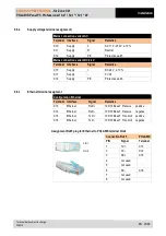
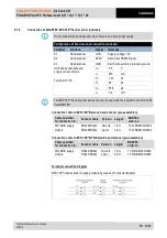
6.8.2
Back-up fuse
In the DC variant The POLARIS PROFESSIONAL Panel PC series is protected internally
by a 4-A time-lag fuse and in the AC variant it is protected by a 1.6 A time-lag fuse.The fuse
may be triggered in the case of voltage dips or undervoltage.
Internal fuse
I2 value
External fuse
Little fuse
1.6 A T
1500A@250VAC
6.83 A
2
s
Siba 1.6 A F
1500A@250VAC
Siba 2.0 A F
1500A@250VAC
Siba 2.5 A F
1500A@250VAC
Little fuse
2.5 A T
1500A@250VAC
22.29
Eska 1.6 A M
1000A@250VAC
Eska 2 A M
1000A@250VAC
We recommend protecting the POLARIS with an upstream fuse to prevent blowing the
fuse inside the device. Only BARTEC can change the internal fuse.
Upstream fuse for AC: 1.6 A quick-acting (since June 2015: 2.5 A)
DC: 4 A quick-acting.
The I
2
value must be taken into consideration for other versions of fuses.
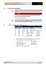
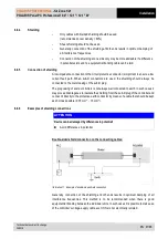
6.8.3
Interference suppression
Certain basic measures must be taken to ensure freedom from interference when the
POLARIS are installed:
–
The interference voltages coupled into the device via power, data and signal line
and the electrostatic voltage caused by contact are to be dissipated through the
equipotential bonding.
–
The installation point should be as far as possible away from fields of
electromagnetic interference. This is especially important if there are frequency
converters in the vicinity. Under certain circumstances will it be advisable to set up
partitions to isolate the graphic display from interference.
–
If inductive devices are fitted in the vicinity (e.g. contactor, relay or solenoid coils),
especially if they are powered from the same source, protective circuits (e.g.
RC elements) must be installed.
–
Power supply and data cables must be laid so as to avoid interference. This can be
achieved, for example, by avoiding laying such cables in close proximity to high-
current carrying cables.


