background image

POLARIS PROFESSIONAL 

- für Zone 1/21 

POLARIS Panel PC Professional 10,4" / 12,1" / 12,1" W


Installation 


Technical data subject to change. 
04/2019 

EN   25/68 


6.2.1


Installation in 2G-/2D-enclosure 

In order to guarantee the IP degree of enclosure protection  = IP54  for installation in 2G 
enclosures of Ex e type of protection (e.g. control equipment), and = IP6X for installation in 
2D  enclosures  in  areas  where  combustible  dusts  exist  -  with  “protection  through  the 
enclosure” type of protection - the reinforcement frame should be used for fastening on the 
front side. 

A reinforcement frame is inserted between the retaining brackets and the enclosure material 
for good transmission of the clamping force. This ensures even transmission of force. 


For POLARIS built into the enclosure door 

The  open  door  must  be  supported  and  secured  during  the  installation  and  servicing 
phase. Otherwise the wall thickness specified may lead to the door sagging slightly when 
open. 


DANGER 

If there is no reinforcement frame, it will not be possible to maintain the  
IP protection. There is a risk of fatal injury in an explosive atmosphere! 


Only use enclosure with at least 2 mm wall thickness. 


Insert the reinforcement frame between the holder and the enclosure. 


Reinforcement frame for maintenance of protection class IP65 

POLARIS 15″ / 15" Sunlight 

05-0205-0009 

POLARIS  17.3″  

05-0205-0013 

POLARIS  19.1″  

05-0205-0010 

POLARIS 24″ 

05-0205-0012 

Fit the reinforcement frame 


Illustration 5: Minimum installation depth and mounting reinforcement frame 

Summary of Contents for POLARIS PROFESSIONAL 17-71V1 Series

Page 1: ...Status 17 April 2019 Reservation Technical data subject to change without notice Changes errors and misprints may not be used as a basis for any claim for damages Content Pages English 1 69 GmbH Max E...

Page 2: ......

Page 3: ...POLARIS PROFESSIONAL for Zone 1 21 POLARIS Panel PC Professional 15 up to 24 Table of Contents Technical data subject to change 04 2019...

Page 4: ...ssional 15 11 4 1 3 Characteristics POLARIS Panel PC Professional 15 Sunlight 11 4 1 4 Characteristics POLARIS Panel PC Professional 17 3 12 4 1 5 Characteristics POLARIS Panel PC Professional 19 1 12...

Page 5: ...i keyboard to the POLARIS optional 41 6 7 2 Ex i USB interface for BARTEC Ex i memory stick 42 6 7 3 Ex d socket optional 42 6 7 4 Connection of a BARTEC BCS 160ex hand scanner optional 43 6 7 5 Fibre...

Page 6: ...Professional 15 up to 24 Technical data subject to change 04 2019 10 3 1 Instructions for repairs 63 11 Disposal 63 12 Dispatch and packaging instructions 63 13 Accessories spare parts 64 14 Order nu...

Page 7: ...blank...

Page 8: ......

Page 9: ...and the strict compliance with it is essential for safe installation and commissioning Accidents injuries and material damage can be avoided by circumspect handling and systematically following the in...

Page 10: ...BARTEC GmbH also apply The current versions of the datasheets operating instructions certificates and EU declarations of conformity can be downloaded from www bartec de or may be requested directly fr...

Page 11: ...ng it with a dry cloth or cleaning it Do not open devices in a hazardous area The general statutory regulations or directives relating to safety at work accident prevention and environmental protectio...

Page 12: ...1 6 5 Commissioning It must be checked that all components and documents are available before commissioning 1 7 Labelling test certificate and standards The device features an explosion protection la...

Page 13: ...storage assembly commissioning operation and maintenance Structural modifications without our prior authorisation Inadequate monitoring of components that are subject to wear Repairs done incorrectly...

Page 14: ...e pre installed multi lingual Windows 7 Ultimate operating system optional Windows 10 IoT LTSB allows the use of its standard visualisation or the BMS Graf pro 7 visualisation software from BARTEC Thi...

Page 15: ...as a ready made system solution in a stainless steel enclosure for wall floor or table mounting For particularly harsh areas of use with temperatures as low as down to 40 C we equip the POLARIS series...

Page 16: ...op pr IIC T4 Ex tb IIIC T120 C Db Certification IECEx IBE 11 0007X Standards in accordance with EMC Directive 2014 34 EU IEC 60079 0 2011 Edition 6 IEC 60079 1 2014 06 Edition 6 IEC 60079 5 2015 Edit...

Page 17: ...rtificates and labeling on request INMETRO 11 UL BRHZ 0131X Customs Union Russia EAC TC RU C DE GB06 B 00334 Korea KTL 14 KB4BO 0258X India CCEs P261984 China NEPSI GYJ18 1382X America CSA 70010166 Mo...

Page 18: ...eT 1 x Ex e RS422 1 x Ex e USB 1 x Ex i USB for Ex i memory stick 2 x Ex i for PS 2 for intrinsically safe keyboard and mouse Optional interface modules 1 x Ex i Supply module for hand held scanner 1...

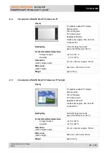
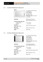
Page 19: ...20 C to 50 C 0 C to 50 C Dimensions width x height x depth 411 mm x 332 mm x approx 135 mm Wall cut out width x height 394 5 mm x 315 5 mm 0 5 mm Weight approx 23 kg 4 1 3 Characteristics POLARIS Pane...

Page 20: ...Operation 20 C to 50 C 0 C to 50 C Dimensions width x height x depth 503 mm x 314 mm x ca 135 mm Wall cut out width x height 489 mm x 300 mm 0 5 mm Weight approx 33 kg 4 1 5 Characteristics POLARIS Pa...

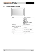
Page 21: ...isplay Full HD resolution 1920 x 1080 pixels 16 7 million colours Brightness 300 cd m2 Visible surface approx 521 x 299 mm Contrast 3000 1 Backlighting LED technology Service life approx 40 000 hours...

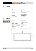
Page 22: ...117 X Ex protection type IECEx Ex ib IIC T4 Gb Ex ib IIIC T120 C Db Certification IECEx IBE 11 0007X More test certificates www bartec de 4 2 2 General data Construction Front panel fitting Material P...

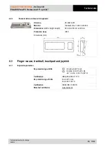
Page 23: ...301 AISI 304 Dimensions width x height x depth 600 mm x 85 mm x 220 mm Protection class IP65 Dimensions mm 4 3 Finger mouse trackball touchpad and joystick 4 3 1 Explosion protection Ex protection typ...

Page 24: ...Trackball Static Dynamic IP65 front site IP65 front site IP51 front site Dimensions width x height 130 mm x 170 mm Wall cut out width x height 100 mm x 140 mm Dimensions and wall cut out mm 4 3 3 Vari...

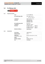
Page 25: ...IBExU 05 ATEX 1117 X Standards EN 60079 0 2009 EN 60079 11 2012 EN 60079 31 2009 Ex protection type IECEx Ex ib IIC T4 Certification IECEx IBE 11 0007X Standards IEC 60079 0 2007 Edition 5 IEC 60079 1...

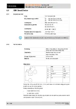
Page 26: ...nstallation in 2G 2D 3G or 3D enclosure Connection via USB Ex e 4 5 2 Technical data Fastening M30 x 1 5 suitable for fixing holes 30 3mm with recess for anti twist safeguard Installation Wall thickne...

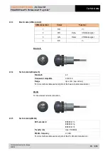
Page 27: ...data signal 4 BK V Bluetooth 4 5 4 Technical data Bluetooth Bluetooth 4 0 Downward compatible 2 0 2 1 3 0 Range Up to 10m open terrain For more technical data see description of the bluetooth stick m...

Page 28: ...onal 15 up to 24 EN 20 68 Technical data subject to change 04 2019 4 6 Product labelling Example Type label with labelling of international approvals Optional Label for other certification exsample IM...

Page 29: ...is heavy 23 38 kg There is a risk of injury if it is lifted or moved incorrectly You will need help from others when transporting it 5 2 Intermediate storage ATTENTION Damage to property through inco...

Page 30: ...tion 1 x ring spanner 7 mm POLARIS accessories 1 x socket wrench 5 5 mm System solution in an Exklusive II 1 x hex key 5 mm to fix the supporting enclosure system in place 5 4 1 Installation options T...

Page 31: ...tential bonding The POLARIS Series is approved for an ambient temperature of from 0 C to 50 C or from 20 C to 60 C and a relative air humidity of from 5 to 95 without condensation 6 1 Requirements The...

Page 32: ...age from condensation or overheating Avoid direct sunlight Remedy e g shelter with sufficient air circulation Remove condensation on the POLARIS immediately A POLARIS built into an enclosure must be h...

Page 33: ...ransmission of the clamping force This ensures even transmission of force For POLARIS built into the enclosure door The open door must be supported and secured during the installation and servicing ph...

Page 34: ...l enclosure Exclusive II The POLARIS is available as a ready made system solution in a stainless steel enclosure e g Exclusive II for floor wall or table mounting CSA approval The CSA approval for the...

Page 35: ...through the cable glands provided into the enclosure Ensure there is sufficient length 6 Mount the enclosure on the supporting system 7 Open the terminal compartments on the POLARIS and feed the suppl...

Page 36: ...erson can lay the supply and data line s in the supporting system Make sure that your fingers do not get caught between the swivel adapter and the enclosure as you set up the POLARIS CSA approval The...

Page 37: ...he entire installation of the intrinsically safe circuits The safety and accident prevention regulations applicable to the respective individual case must be observed Devices must be properly installe...

Page 38: ...atmosphere Do not open the locking screw DANGER Non certified cable glands and non sealed cable entries endanger the IP protection and accordingly the protection against explosions There is a risk of...

Page 39: ...ainst self loosening Stainless steel enclosure Exclusive II Attach equipotential bonding to the enclosure All moving parts must be earthed Secure PE conductor connections against self loosening Work s...

Page 40: ...ined The terminal area of the M20 cable glands is printed on the cable glands A different terminal area may only be substituted with a cable gland that complies with the current version of the approva...

Page 41: ...nterface Signal Remarks X10 Supply DC 24 V 10 X11 Supply 0 Volt X12 Supply PE Protective earth 6 6 3 Ethernet terminal assigment Configuration Ethernet Terminal Interface Signal Remarks X13 Ethernet R...

Page 42: ...Transmission cableI Input X21 Interface COM 1 RxD B RxD Receiving cable Input X22 Interface COM 1 RxD A RxD Receiving cable Input Connection PLC with RS422 interface to POLARIS Maximum length of the...

Page 43: ...tstelle Signal Bemerkungen X17 N C X18 N C X19 Interface COM 1 TxD B TxD to PLC X20 Interface COM 1 TxD A TxD X21 N C X22 N C X23 N C X24 N C X25 Interface COM 1 RxD B RxD to next POLARIS X26 Interfac...

Page 44: ...2 X20 Interface COM 1 Termination A2 Bridge for terminating network A1 A2 X21 Interface COM 1 Termination B1 Bridge for terminating network B1 B2 X22 Interface COM 1 Termination A1 Bridge for terminat...

Page 45: ...face COM 1 20 mA Signal power source for receiver X23 Interface COM 1 GND Signal ground for transmitter X24 Interface COM 1 Tx Emitter X25 Interface COM 1 Tx Collector X26 Interface COM 1 20 mA Signal...

Page 46: ...ot connected X18 Not connected X19 Not connected X20 Not connected X21 Not connected X22 Not connected X23 Not connected X24 Interface COM 1 RxD Receive X25 Interface COM 1 TxD Transmit X26 Interface...

Page 47: ...19 Interface COM 1 B Termination X20 Interface COM 1 A Termination X21 Interface COM 1 LTG B Out B X22 Interface COM 1 LTG A Out A X23 Interface COM 1 LTG B In B X24 Interface COM 1 LTG A In A X25 Int...

Page 48: ...n Colour Function X23 1 RD VCC 5 V X26 4 BK GND X25 3 GN Data X24 2 WH Data The maximum length of a lead should not exceed 2 m Maximum current 300 mA When configuration the HMI Outside the Ex area it...

Page 49: ...tective enclosure with protection class of at least IP20 6 7 1 Connection of Ex i keyboard to the POLARIS optional PS 2 for input devices Terminal Interface Colour Signal Remarks X4 PS 2 WH BR VCC Sup...

Page 50: ...Cable name Inline E258105 AWM STYLE 2725 80 C 30V VW 1 28AWGX1P 24AWGX2C USB 2 0 High speed cable 6 7 3 Ex d socket optional DANGER Live plug in connections Risk of fatal injury if opened in an explos...

Page 51: ...X3 U0 5 5 V I0 440 mA P0 1 25 W Ri 25 a C0 55 8 F L0 0 2 mH The BCS 160ex hand scanner series can only be used with the original connection cable from BARTEC Connection cable to BCS 160ex Barcode hand...

Page 52: ...100 MBit s Permissible ambient temperatures Storage transport Operation 20 C bis 80 C 0 C bis 55 C Multi mode Converter Range Fibre type Min transmitting power Min sensitivity Wave length Plug connec...

Page 53: ...oltage drop on the supply cable and correct if necessary The voltage drop in the DC variant of the supply line is calculated with the following formula U Voltage drop on the supply line at power suppl...

Page 54: ...ing The I2 value must be taken into consideration for other versions of fuses 6 8 3 Interference suppression Certain basic measures must be taken to ensure freedom from interference when the POLARIS a...

Page 55: ...nnected to the metal casing of the sub D plug The plug casing of some controllers is not always well connected to earth In such cases it may prove advantageous to insulate the shielding from the sub D...

Page 56: ...ust be used Before the equipment goes into service the directions from the controller manufacturer regarding proper assembly and operation must be read carefully They should then be applied taking ful...

Page 57: ...POLARIS PROFESSIONAL for Zone 1 21 POLARIS Panel PC Professional 15 up to 24 Installation Technical data subject to change 04 2019 EN 49 68...

Page 58: ...1 Final inspection Check the following requirements before commissioning the device Only open the ex e terminal compartment with terminals for the supply and data line s once it has been ensured that...

Page 59: ...this system as an office PC 8 2 Commissioning Software 8 2 1 Windows 10 Iot Enterprise LRSB The devices are delivered with active writing filter UWF This UWF prevents that changes in the disk drive C...

Page 60: ...the devices which serves the disregard of the device in the work state In case of a mistake every device can be booted up in the Recovery mode to move afterwards the operating system into the work sta...

Page 61: ...nd are ready for use the Recovery engine will check in the background whether the applications necessary for the device tools and drivers exist All information about internal expiries is indicated in...

Page 62: ...Ultimate or standard of operating system the pictures look similar Besides all background expiries are identical with the differences it is only about inscriptions The operation navigating over windo...

Page 63: ...the next line how far the process is already concluded As a rule all time luxurious processes are computable The progress beam in the middle of the window returns the graphic picture of the percent v...

Page 64: ...e unpacked and transferred on the operating system partition Illustration 19 Transferred by system files on operating system partition Transferring of system files is the last process with the Widerhe...

Page 65: ...ases During the first phase components of the device are recognised the hardware and are integrated into the operating system During the second phase the final settings are put Between the phases or w...

Page 66: ...r suchlike and or in the company network 8 4 3 Switching off and shutting down Irrespective of the application the Microsoft Windows operating system saves important data in the working memory during...

Page 67: ...change 04 2019 EN 59 68 8 5 Network Ethernet setup 8 5 1 Requirements Network Ethernet setup Physical connection connection of Ethernet cable to a network e g switch hub server Go to Start Control pa...

Page 68: ...ernet Protocol figure 2 the function is activated Figure 1 Figure 2 The chart figure 3 appears when the network and a DHCP server are available Configuration example figure 4 when no DHCP server is av...

Page 69: ...ion of the power supply External back up fuse has tripped Check the fuse Internal fuse has tripped Return to the manufacturer Device malfunction Return to the manufacturer Display turns on and off con...

Page 70: ...t conditions DANGER Prevent electrostatic charging in hazardous potentially explosive areas There is a risk of a fatal injury in an explosive atmosphere Take devices out of hazardous areas before wipi...

Page 71: ...e intended as professional electric devices for business use only referred to as B2B devices under the WEEE Directive The WEEE directive sets the framework for waste electric and electronic equipment...

Page 72: ...r keyboard and trackball joystick 1 8 m 03 0068 0172 3 0 m 05 0068 0205 for keyboard and touchpad 1 8 m 03 0068 0183 3 0 m 03 0068 0206 Ex i memory stick 17 71VZ 5000 0100 Enclosure Exclusive II POLAR...

Page 73: ...RIS Panel PC Professional 15 up to 24 Additional information Technical data subject to change 04 2019 EN 65 68 14 Order numbers POLARIS Panel PC 15 POLARIS Panel PC 15 Sunlight POLARIS Panel PC 19 POL...

Page 74: ...Additional information POLARIS PROFESSIONAL for Zone 1 21 POLARIS Panel PC Professional 15 up to 24 EN 66 68 Technical data subject to change 04 2019 15 Additional information...

Page 75: ...POLARIS PROFESSIONAL for Zone 1 21 POLARIS Panel PC Professional 15 up to 24 Declaration of conformity Technical data subject to change 04 2019 EN 67 68 16 Declaration of conformity...

Page 76: ...Declaration of conformity POLARIS PROFESSIONAL for Zone 1 21 POLARIS Panel PC Professional 15 up to 24 EN 68 68 Technical data subject to change 04 2019 All certificates see www bartec de...

Reviews: