Manual 2100-620A
Page
43 of 107
2. 24VDC from terminal N07 (Blower Motor Start
Relay)
3. 0-10VDC signal from terminal Y1 (Motor Speed)
Loss of Utility Power
When AC power is lost to the unit (no shore power,
no generator), the AC power loss relay will send a
digital input to terminal DI 1, alerting the board. If
the temperature outside is warmer than the shelter
internal temperature, the units will remain static. If
the temperature outside is cooler than the internal
temperature and there is a generated cooling call, the
control board will send:
1. 2-10VDC Signal from terminal Y2 (Damper Signal)
-
Modulates damper to achieve 55°F at supply
air temperature sensor
2. 24VDC from terminal N07 (Blower Motor Start
Relay)
3. 0-10VDC signal from terminal Y1 (Motor Speed)
Special Considerations
• Compressor Run Time – Once activated, the
compressor will run for a minimum of 5 minutes,
regardless of setpoint (PLC programming)
• Compressor Off Time – Once deactivated, the
compressor will not start again for a minimum of 2
minutes.
• High Pressure Situation – The high pressure switch
routes through the compressor control module
(CCM), which allows one switch opening followed
by a delay (soft lockout) of at least 2 minutes
before trying again. If the switch is still open—or
opens again on the same call—the CCM locks out
the compressor and outdoor fan. Additionally, the
CCM will send 24V to the high pressure alarm
relay, which will then send a digital input to the DI
3 terminal.
• Low Pressure Situation – The low pressure switch
is routed directly to DI 4 on the board and has a
very specfic scheme of operation:
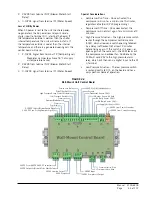
FIGURE 2.2
Wall-Mount Unit Control Board
Power Loss Relay
Dirty Filter Switch
High Pressure/Comp Control Module
Low Pressure Switch
Common
Damper Blade Switch
0-10VDC Indoor Blower Speed Signal
2-10VDC Free-Cooling Damper Signal
Common
Common
24VDC From 48VDC-24VDC Converter
24VDC Output to Blower Motor Start Relay
24VAC Heating Output
24VAC Input
24VAC Input
24VAC Compressor Output
– Communication Wire
+ Communication Wire
24VDC to OA Humidity Sensor
Ground
OA Hum Sensor 4-20mA
RA Temp Sensor 10kΩ
OA Temp Sensor 10kΩ
Supply Air Sensor 10kΩ
+24VDC from Power Converter
–24VDC from Power Converter
Freezestat Sensor 10kΩ
Summary of Contents for D36A2P/BLD.10304
Page 6: ...Manual 2100 620A Page 6 of 107 ...
Page 7: ...Manual 2100 620A Page 7 of 107 SECTION 1 INSTALLATION INSTRUCTIONS ...
Page 39: ...Manual 2100 620A Page 39 of 107 SECTION 2 SERVICE INSTRUCTIONS ...
Page 73: ...Manual 2100 620A Page 73 of 107 SECTION 3 PARTS MANUAL ...
Page 90: ...Manual 2100 620A Page 90 of 107 ...
Page 91: ...Manual 2100 620A Page 91 of 107 SECTION 4 APPENDICES ...


