


Manual 2100-620A
Page
29 of 107
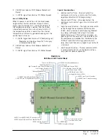
1. Using the field-provided shielded cable, make a small service loop after entering the controller and attach the provided
EMI filter at the intersection of the loop.
FIGURE 1.22
Communication Wiring: Termination at the Controller
2. Connect one wire to terminal #33 (negative), the other wire to terminal #34 (positive) and the drain wire to ground
terminal #35.
-
+
G
-
+
G
To Wall-Mount Unit 1
Control Board RS485
Summary of Contents for D36A2P/BLD.10304
Page 6: ...Manual 2100 620A Page 6 of 107 ...
Page 7: ...Manual 2100 620A Page 7 of 107 SECTION 1 INSTALLATION INSTRUCTIONS ...
Page 39: ...Manual 2100 620A Page 39 of 107 SECTION 2 SERVICE INSTRUCTIONS ...
Page 73: ...Manual 2100 620A Page 73 of 107 SECTION 3 PARTS MANUAL ...
Page 90: ...Manual 2100 620A Page 90 of 107 ...
Page 91: ...Manual 2100 620A Page 91 of 107 SECTION 4 APPENDICES ...


