


7. Image Menu
The objective of input balancing
The objective in input balancing is to “set” the same black level and the same white level for the three colors of a particular input
source.
Black level setting : brightness
White level setting : contrast
The same absolute black and white level for the three colors allows the same reference for Brightness and contrast control of the
picture.
These two references also set the range in which the ADC will work for that particular source (this explains also why each input
balance setting is linked to a particular source and thus saved in the image file).
How can it be done ?
To balance the three color signals of a particular source there are conditions; in fact we must know the black and the white level of
the source i.e. :
1.
The source in question must be able to generate a white signal, ideally a 100% white (background) full screen pattern.
2.
The source in question must be able to generate a black signal, ideally a 100 % black (background) full screen pattern.
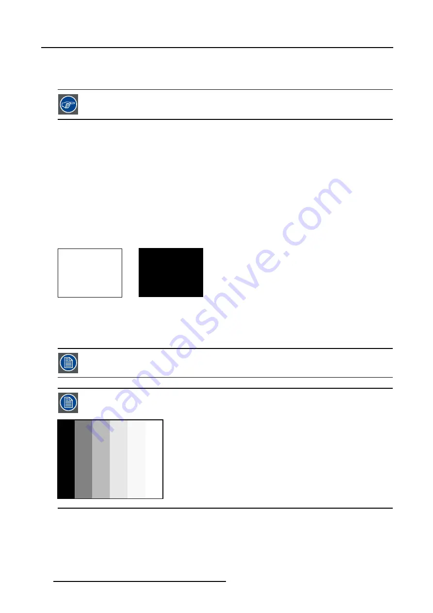
A
B
Image 7-1
White balance : In the projector, we will set the contrast for each color until we get a 100% light output picture when projecting a
100% white image (image A)
Black balance : In the projector, we will set the brightness for each color until we get a 0% light output picture when projecting a
100% black image (image B).
The changeover from min to max is indicated by the apparition of bright spots also called “digital noise”.
An alternative to a full screen White/black pattern is the standard gray scale pattern, the white bar will be used
for white balance and the black bar for black balance.
Image 7-2
How to Start Up Input Balance?
1. Push the cursor key
←
or
→
to highlight
Image
in the menubar.
2. Push the
↓
key to pull down the
Image
menu.
3. Push the cursor key
↑
or
↓
to highlight
Input Balance
.
4. Push the
→
key to pull down the
Input Balance
menu. (image 7-3)
44
R5976870 BARCOREALITY SIM 5PLUS/SIM 5R 04/04/2007
Summary of Contents for R9040380
Page 1: ...BarcoReality SIM 5plus SIM 5R Owner s Manual R9040380 R9040381 R5976870 03 04 04 2007...
Page 4: ......
Page 10: ...1 Safety Instructions 6 R5976870 BARCOREALITY SIM 5PLUS SIM 5R 04 04 2007...
Page 28: ...3 Installation Guidelines 24 R5976870 BARCOREALITY SIM 5PLUS SIM 5R 04 04 2007...
Page 36: ...4 Connections 32 R5976870 BARCOREALITY SIM 5PLUS SIM 5R 04 04 2007...
Page 59: ...7 Image Menu Image 7 22 R5976870 BARCOREALITY SIM 5PLUS SIM 5R 04 04 2007 55...
Page 72: ...7 Image Menu Image 7 55 Image 7 56 68 R5976870 BARCOREALITY SIM 5PLUS SIM 5R 04 04 2007...
Page 163: ...8 Geometry Menu Image 8 162 Image 8 163 R5976870 BARCOREALITY SIM 5PLUS SIM 5R 04 04 2007 159...
Page 164: ...8 Geometry Menu 160 R5976870 BARCOREALITY SIM 5PLUS SIM 5R 04 04 2007...
Page 186: ...10 Lamps Menu 182 R5976870 BARCOREALITY SIM 5PLUS SIM 5R 04 04 2007...
Page 198: ...12 Display Setup Menu 194 R5976870 BARCOREALITY SIM 5PLUS SIM 5R 04 04 2007...
Page 216: ...13 Installation Menu 212 R5976870 BARCOREALITY SIM 5PLUS SIM 5R 04 04 2007...
Page 218: ...14 Service Menu Image 14 2 214 R5976870 BARCOREALITY SIM 5PLUS SIM 5R 04 04 2007...
Page 220: ...15 Adjustment Menu 216 R5976870 BARCOREALITY SIM 5PLUS SIM 5R 04 04 2007...
Page 226: ...A Standard Image Files 222 R5976870 BARCOREALITY SIM 5PLUS SIM 5R 04 04 2007...
Page 232: ...B Scheimpflug Lens Adjustment 228 R5976870 BARCOREALITY SIM 5PLUS SIM 5R 04 04 2007...
Page 236: ...C Calibrate Measured Values 232 R5976870 BARCOREALITY SIM 5PLUS SIM 5R 04 04 2007...
Page 240: ...D Software Update 236 R5976870 BARCOREALITY SIM 5PLUS SIM 5R 04 04 2007...
Page 242: ...E Troubleshoot 238 R5976870 BARCOREALITY SIM 5PLUS SIM 5R 04 04 2007...


