background image

3. Physical installation

3.7

Power loop through to the projector electronics

This procedure explains how to provide the projector electronics with power in case no UPS unit is used.
Note that the projector is by default con

fi

gured for use without UPS. So, the short power link cable is already

installed.

Necessary tools

No tools.

Necessary parts

Short power link cable with plug type C13/C14

How to loop through the power

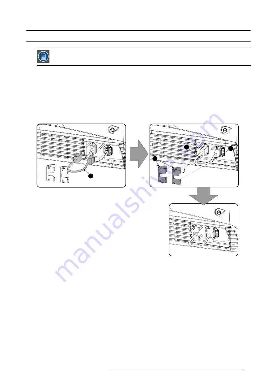
1. Plug in the short power cable (1) which was delivered with the projector.

Warning:

Always use the Barco short power cable which is delivered with the projector.

1

2

3

3

Image 3-16
Power loop through connection

2. Secure both plugs of the short cable with a

fi

xation spring (2). Handle as follow:

-

Squeeze the

fi

xation spring together.

-

Slide the

fi

xation spring on the

fi

xation pins (3) while squeezing together and push it against the power plug.

-

Release the

fi

xation spring.

R5905963 PROMETHEUS SERIES 09/03/2015

35

Summary of Contents for Prometheus I

Page 1: ...Prometheus series Installation safety manual R5905963 00 09 03 2015 ...

Page 2: ...Barco nv Noordlaan 5 B 8520 Kuurne Phone 32 56 36 82 11 Fax 32 56 36 883 86 Support www barco com en support Visit us at the web www esterline com Printed in Belgium ...

Page 3: ...ed terms of guarantee On receipt the purchaser must immediately inspect all delivered goods for damage incurred during transport as well as for material and manufacturing faults Barco must be informed immediately in writing of any complaints The period of guarantee begins on the date of transfer of risks in the case of special systems and software on the date of commissioning at latest 30 days aft...

Page 4: ...e code contained in this product shipped to you on CD please contact Barco The cost of preparing and mailing a CD will be charged Trademarks Brand and product names mentioned in this manual may be trademarks registered trademarks or copyrights of their respective holders All brand and product names mentioned in this manual serve as comments or examples and are not to be understood as advertising f...

Page 5: ...m manual XL Lamp House 48 4 7 Installation of the xenon lamp in manual S M Lamp House 53 4 8 Installation of the xenon lamp in manual XL Lamp House 58 4 9 Check if anode support must be provided with a plain washer 64 4 10 Installation of the Lamp House 65 4 11 Resetting the lamp parameters 66 4 12 Realignment of the lamp in its reflector manual Lamp House 67 5 Lenses lens holder 69 5 1 Available ...

Page 6: ...el 154 11 6 Cooling liquid refill 155 11 7 Authorization to clear security warning on the projector 156 12 Convergence 157 12 1 Open the sealed compartment 158 12 2 Close the sealed compartment 160 12 3 Convergence controls 161 12 4 Red on blue convergence 163 12 5 Green on blue convergence 164 13 Specifications 165 13 1 Specifications of the Prometheus I 166 13 2 Specifications of the Prometheus ...

Page 7: ...document to the term Prometheus series means that the content is applicable for following Barco products Prometheus I Prometheus II Barco provides a guarantee relating to perfect manufacturing as part of the legally stipulated terms of guar antee Observing the specification mentioned in this chapter is critical for projector performance Neglecting this can result in loss of warranty Model certific...

Page 8: ...ilt in accordance with the requirements of the international safety standards IEC60950 1 EN60950 1 UL60950 1 and CAN CSA C22 2 No 60950 1 which are the safety standards of information technology equipment including electrical business equipment These safety standards impose important requirements on the use of safety critical components materials and insulation in order to protect the user or oper...

Page 9: ...n only be gained by skilled persons installer or service personnel or persons who have been instructed and trained by a skilled person The persons must have been instructed about the reasons for the restriction applied to the location and about the precautions that shall be taken Access is only possible through the use of the tool or lock and key or other means of security and is controlled by the...

Page 10: ...ust be incorporated externally to the equipment for removal of the power to the pro jector mains terminals Disconnect the power to the projector mains terminals and unplug the power cord at UPS INLET for removal of all power from the projector High leakage current Earth connection essential before connecting supply Do not allow anything to rest on the power cord Do not locate this product where pe...

Page 11: ... can be accomplished by wearing safety glasses that are designed to provide UV protection In addition to the UV the visible light from the lamp is intense and should also be considered when choosing protective eye wear Exposure to UV radiation some medications are known to make individuals extra sensitive to UV radiation The American Conference of Governmental Industrial Hygienists ACGIH recommend...

Page 12: ...ave to ship your equipment For maximum protection repack your set as it was originally packed at the factory Disconnect the power to the projectors mains terminals before cleaning Do not use liquid cleaners or aerosol cleaners Use a damp cloth for cleaning Never use strong solvents such as thinner or benzine or patrol or abrasive cleaners since these will damage the cabinet Stubborn stains may be ...

Page 13: ... authorized protective clothing MUST be worn Authorized protective clothing for xenon lamp handling WARNING Always wear face protection full face shield when handling xenon lamps WARNING Always wear protective clothing welder s jacket when handling xenon lamps WARNING Always wear clean leather gloves with wrist protectors when handling xenon lamps To prevent battery explosion Danger of explosion i...

Page 14: ...e assumed to stand or 1 meter SW image 1 1 below or in lateral separation from any place where such persons are assumed to be See image 1 1 RA TH PR RZ HD SW 1m SW SW SW HD SH RA TH RZ SH B TOP VIEW A SIDE VIEW Image 1 1 A Side view B Top view RA Restricted Access location booth area of projector PR Projector TH Theater RZ Restriction Zone in the theater SH Separation Height Must be minimum 2 mete...

Page 15: ...1 Safety PR Image 1 2 R5905963 PROMETHEUS SERIES 09 03 2015 11 ...

Page 16: ... 5 HD m TR HD HB lens HD HC lens Image 1 3 HD in meter for the Prometheus I equipped with HD HB or HD HC type lens Prometheus II Hazard Distance 0 0 5 1 1 5 2 2 5 3 1 0 1 3 1 5 1 8 2 0 2 3 2 5 2 8 3 0 3 3 3 5 3 8 4 0 4 3 4 5 4 8 5 0 5 3 5 5 HD m TR HD HB lens HD HC lens Image 1 4 HD in meter for the Prometheus II equipped with HD HB or HD HC type lens 12 R5905963 PROMETHEUS SERIES 09 03 2015 ...

Page 17: ... image size ambient light level projector placement and type of screen to use are critical to the optimum use of the projection system Barco provides a guarantee relating to perfect manufacturing as part of the legally stipulated terms of guar antee Observing the specification mentioned in this chapter is critical for projector performance Neglecting this can result in loss of warranty Overview Sa...

Page 18: ...n only be gained by skilled persons installer or service personnel or persons who have been instructed and trained by a skilled person The persons must have been instructed about the reasons for the restriction applied to the location and about the precautions that shall be taken Access is only possible through the use of the tool or lock and key or other means of security and is controlled by the...

Page 19: ...type of power cord The cross sectional area of the conductors in the power supply cord shall not be less than 4 mm or 10 AWG minimum 300V To protect operating personnel the National Electrical Manufacturers Association NEMA recommends that the instrument panel and cabinet be grounded In no event shall this projector be operated without an adequate cabinet ground connection The AC supply must be in...

Page 20: ...ad of the system Measures to resolve radio interference Operation of this equipment in a residential area may cause radio interference Possible interference shall be solved by one of the following non limitative product installation measures Create more separation distance between projector and interfered device Change direction of the interfered device Electromagnetic shielding of the projection ...

Page 21: ...ton box and wooden pallet in a safe manner without damaging the projector After unpacking let the projector acclimatises to a room temperature higher then 10 C 50 F and lower then 35 C 95 F Neglecting this may result in a start up failure of the Light Processor Unit How to unpack 1 Loosen the banding by pulling the free end of the banding loop in the clip Take off the box cover Image 2 1 Open band...

Page 22: ... Remove the inner carton box Image 2 3 Remove inner carton 4 Loosen the banding by pulling the free end of the banding loop in the clip Take off the upper carton plate 1 Remove from the wooden pallet 2 18 R5905963 PROMETHEUS SERIES 09 03 2015 ...

Page 23: ...ge 2 4 Remove wooden pallet 5 Take the projector from the wooden board by gripping the bottom of the projector and place the projector on the pedestal Image 2 5 Remove projector R5905963 PROMETHEUS SERIES 09 03 2015 19 ...

Page 24: ...ojector it is recommended to check if all following items where included One short power link cable mono phase in case no UPS is used Installed on projector This manual installation manual Safety manual The projector lens and xenon lamp are not included in the package of the projector Mechanical check This check should confirm that there are no broken knobs or connectors that the cabinet and panel...

Page 25: ... Panel page 121 8 Fence off the exclusion zone if needed See chapter Safety training to be provided by the installer page 14 exclusion zone 9 Alignment of the projected image on the screen The projector can now be switched on to project its first image test pattern on the screen Then the image can be aligned with the screen size of the application Follow the next steps to achieve that a Place the ...

Page 26: ...or is equipped with a HD SDI input module apply a single or dual channel SMPTE HD SDI source to the input ports of the HD SDI input module and start up the projector See chapter Input communication page 89 Use the Communicator Touch Panel to configure the applied source See the user guide of the Communicator Touch Panel for more detailed information In case the projector is equipped with an Integr...

Page 27: ...the Prometheus at port window Installation of the exhaust system Access to the power connection Power input setup only for Prometheus II Connecting the Prometheus I projector with the power net Connecting the Prometheus II projector with the power net Power loop through to the projector electronics Connecting a UPS to the projector electronics R5905963 PROMETHEUS SERIES 09 03 2015 23 ...

Page 28: ...niversal pedestal has a separate compartment to install the UPS unit if available for the Prometheus Futhermore the universal pedestal contains a standard 19 rack to build in the projector periph erals like alternative content switchers e g ACS 2048 Necessary tools 14 mm wrench 17 mm wrench Projector centering 1 If the projector is standalone in front of the port window center the projector with t...

Page 29: ...ered with and parallel to the screen This orientation helps to ensure optimized lens performances with minimal offset If this position is not possible such as when the projector is significantly higher than the center of the screen it is better to rely on offset rather than extra tilt 1 Before adjusting tilt make sure the projector is as well centered with the theatre screen as possible for your i...

Page 30: ...llation 90 Inclined screen Image 3 4 Projector tilting Barco offers a pedestal for the Prometheus This universal pedestal allows you to easily tilt the projector forward up to 6 26 R5905963 PROMETHEUS SERIES 09 03 2015 ...

Page 31: ...r duct This size must be used throughout the entire system and installed to eliminate any possibility of downdraft or rain dripping into the lamp house The exhaust fan must be capable of removing minimum 10m3 min 350 CFM measured at the projector s exhaust opening A built in vane switch detects if the airflow in the exhaust opening is high enough When something goes wrong one of the following erro...

Page 32: ... fan may electrically be connected with the projector When that is done the blower starts working when the lamp is switched on and stops working after the cool period is completed The power socket is located next to exhaust output and may only be used to connect the external exhaust fan No connection with other devices is allowed The exhaust outlet delivers maximum 3A 200 240V at 50 60Hz The exter...

Page 33: ...ove the back cover 2 Loosen both captive screws 1 1 Image 3 7 Power connection cover captive screws 1 Image 3 8 Power connection cover captive screws 3 Slide off the power connection cover Image 3 9 Terminal strip accessible The terminal strip and connection plate is accessible R5905963 PROMETHEUS SERIES 09 03 2015 29 ...

Page 34: ...age 3 10 Υ Δ connection A Υ connection B Δ connection Necessary tools Flat screw driver Wrench 10 mm Torque wrench 10 mm How to switch from a Υ connection to Δ connection 1 Loosen the 6 top nuts on the Υ Δ configuration block 1 to 6 Y Δ 1 2 3 4 5 6 B A C Image 3 11 Υ to Δ connection 2 Take off the mounted lins A B and C Two links above each other or mounted between the upper and middle pin A B and...

Page 35: ...e 3 12 Δ to Υ connection 2 Take off the mounted links A B and C 3 Connect the right pins together Place 2 links between the upper pin and the middle pin A B and 1 link between the middle pin and the lower pin C R5905963 PROMETHEUS SERIES 09 03 2015 31 ...

Page 36: ...WG min 300V diameter between 11 mm and 21 mm Circuit breaker maximum 40A How to connect 1 Remove the back cover 2 Remove the power input cover 3 Loosen the cable gland fixation ring 1 Note The cable gland 1 is specified for cables with a diameter between 11mm and 21mm 1 Image 3 13 Power cable connection 4 Push the stripped power supply cable through the cable gland When using a flexible power cord...

Page 37: ...PE 230 400V Certified power cable minimum 4 mm or AWG 10 500V rated cable diameter between 11 mm and 21 mm or for 3W PE 208V Certified power cable minimum 4 mm or AWG 10 300V rated cable diameter between 11 mm and 21 mm Circuit breaker maximum 40A How to connect 1 Remove the back cover 2 Remove the power input cover 3 Loosen the cable gland fixation ring 1 Note The cable gland 1 is specified for c...

Page 38: ...ier strip If a neutral conductor is available connect always to the connector indicated with N on the terminal barrier strip Warning Always connect first the PE wire 3W N PE 3W PE L1 L2 L3 N PE L1 L2 L3 PE Image 3 15 Terminal connections 6 Reinstall the power connection cover 34 R5905963 PROMETHEUS SERIES 09 03 2015 ...

Page 39: ...able with plug type C13 C14 How to loop through the power 1 Plug in the short power cable 1 which was delivered with the projector Warning Always use the Barco short power cable which is delivered with the projector 1 2 3 3 Image 3 16 Power loop through connection 2 Secure both plugs of the short cable with a fixation spring 2 Handle as follow Squeeze the fixation spring together Slide the fixatio...

Page 40: ...he front cover can be removed without removing the UPS INLET cable B 1 2 A B Image 3 17 UPS connection 3 Secure the UPS inlet socket with a fixation spring Handle as follow Squeeze the fixation spring together Slide the fixation spring on the fixation pins while squeezing together and push it against the power plug Release the fixation spring 4 Install on the power outlet the second fixation sprin...

Page 41: ... to be dismantled or whenever the protective container or cloth has to be removed from the xenon lamp authorized protective clothing MUST be worn WARNING Always wear face protection full face shield when handling xenon lamps WARNING Always wear protective clothing welder s jacket when handling xenon lamps WARNING Always wear clean leather gloves with wrist protectors when handling xenon lamps Over...

Page 42: ...a level at which the bulb may explode if not handled in strict accordance to the manufacturer s instructions The bulb is stable at room temperature but may still explode if dropped or otherwise mishandled Whenever the lamp house containing a xenon lamp has to be dismantled or whenever the protective container or cloth has to be removed from the xenon lamp authorized protective clothing MUST be wor...

Page 43: ...p Info module 5 Positioning pin 6 UV blocker 7 Cathode connection with SPG 8 Anode connection with SPG 9 Removable front cover 10 Air out let 11 Removable side cover 12 Lamp Info module 13 Lamp House fixation screw 14 Adjustment screw horizontal lamp alignment 15 Lamp cathode fixation screw 16 Adjustment screw for lamp Z alignment 17 Adjustment screw vertical lamp alignment R5905963 PROMETHEUS SER...

Page 44: ...check with the Communicator software if the lamp is listed in the list of supported lamps for this projector Supported lamp types and their respective anode cathode adapters for the S M Lamp House Lamp type Supplier Cathode adapter S M Lamp House Barco Order No 4kW DHP OSRAM XBO R865555K R9855937 3kW DHP OSRAM XBO R865555K R9855938 2kW DHP OSRAM XBO R865555K R9855956 1200W DHP OSRAM XBO R865555K R...

Page 45: ...ftware if the lamp is listed in the list of supported lamps for this projector Supported lamp types and their respective anode cathode adapters for the XL Lamp House Lamp type Supplier Cathode adapter Anode adapter Anode adaptation bushing Barco Order No 3000W DHS OFR OSRAM XBO R8436061K R859987K R9855950 4500W DHP OFR OSRAM XBO R8436081K R859986K R9855949 6000W DHP OFR OSRAM XBO R8436081K R864132...

Page 46: ...132K Image 4 5 Cathode adapters for manual Lamp House R8436081K R8436101K R8436111K R859984K R8436061K Image 4 6 The shortest cathode adapter R8436101K is no longer needed for xenon lamps supported by Barco For that this adapter has become obsolete 42 R5905963 PROMETHEUS SERIES 09 03 2015 ...

Page 47: ...off and cooled down 2 Remove the cover of the Lamp House compartment 3 Release the two retaining screws reference 1 image 4 7 at the base of the Lamp House Use a 10mm nut driver or a flat screw driver 4 Remove the Lamp House as follows a Grip the Lamp House by the bottom handle and partially slide it out of the lamp compartment b Grip the Lamp House by both handles and remove it completely from th...

Page 48: ...ing MUST be worn WARNING Always wear face protection full face shield when handling xenon lamps WARNING Always wear protective clothing welder s jacket when handling xenon lamps WARNING Always wear clean leather gloves with wrist protectors when handling xenon lamps Necessary tools 5mm Allen wrench Lamp protective container or protective cloth with two binders Flat blade screw driver 2 5mm Allen w...

Page 49: ... 4 Support the xenon lamp inside the Lamp House with one hand while removing the UV blocker assembly from the lamp house Warning Supporting the xenon lamp with one hand prevents the xenon lamp from dropping and colliding with the chassis of the Lamp House Image 4 11 5 Slide out the anode connector from the Lamp House The anode connector remains attached with the lamp anode wire Image 4 12 R5905963...

Page 50: ...st the chassis of the Lamp House Image 4 13 7 Place the xenon lamp in its protective container or wrap the xenon lamp in a protective cloth and secure with two binders Image 4 14 Left Xenon lamp wrapped in a protective cloth Right Xenon lamp captured in a protective container 8 Remove the anode wire lug reference 6 image 4 15 from the anode socket as illustrated Use a 8mm Allen wrench Tip Place th...

Page 51: ...s of canvas or heavy cloth Place it on hard surface and shatter the envelope with a sharp hammer blow DO NOT place a non shattered bulb in any ordinary refuse container CAUTION Small amounts of radioactive material 1000 Bq per lamp are deliberately added to Xenon lamps for functional reasons These lamps are manufactured under regulatory control as consumer product accord ing to IAEA basic safety s...

Page 52: ...ARNING Always wear face protection full face shield when handling xenon lamps WARNING Always wear protective clothing welder s jacket when handling xenon lamps WARNING Always wear clean leather gloves with wrist protectors when handling xenon lamps Necessary tools Two open end wrenches of 22mm 5mm Allen wrench Lamp protective container or protective cloth with two binders Flat blade screw driver 2...

Page 53: ... 4 Support the xenon lamp inside the Lamp House with one hand while removing the UV blocker assembly from the lamp house Warning Supporting the xenon lamp with one hand prevents the xenon lamp from dropping and colliding with the chassis of the Lamp House Image 4 20 5 Slide out the anode connector from the Lamp House The anode connector remains attached with the lamp anode wire Image 4 21 R5905963...

Page 54: ...Place the xenon lamp in its protective container or wrap the xenon lamp in a protective cloth and secure with two binders Image 4 23 Left Xenon lamp wrapped in a protective cloth Right Xenon lamp captured in a protective container 8 Remove the anode wire lug reference 7 image 4 24 from the anode socket Use for that two open ended spanners of 22 mm Hold the first nut reference 5 with one spanner wh...

Page 55: ...illustrated Use a 2 5mm Allen wrench Note Some xenon lamps have a cathode pin with screw threat reference 10 image 4 25 10 9 Image 4 25 10 Remove the anode adapter from the xenon lamp by releasing the hexagon socket head set screw reference 13 image 4 26 of the lamp adapter as illustrated Use for that a 2 5mm Allen wrench 13 Image 4 26 R5905963 PROMETHEUS SERIES 09 03 2015 51 ...

Page 56: ... in any ordinary refuse container CAUTION Small amounts of radioactive material 1000 Bq per lamp are deliberately added to Xenon lamps for functional reasons These lamps are manufactured under regulatory control as consumer product accord ing to IAEA basic safety standard BSS 115 Disposal according to national regulations is required e g in Europe covered by WEEE regulation See also related user m...

Page 57: ...lamps WARNING Always wear clean leather gloves with wrist protectors when handling xenon lamps This procedure assumes that the anode support assembly and the side cover are already removed from the Lamp House due to the removal of the xenon lamp Necessary tools Torque wrench with a 2 5 mm Allen socket Torque Allen key 1 5 mm Allen wrench 22 mm open end wrench Torque wrench with a 22 mm hexagon soc...

Page 58: ...he xenon lamp The serial number of the xenon lamp is engraved in the neck of the xenon lamp 3 Check the cathode connection inside the lamp house Use an 22 mm open end wrench to hold the first nut while fastening the second nut on the rod with a torque of 25Nm 18 4 lbf ft using a torque wrench with 22 mm hexagon socket Ensure that there is a flat washer at both sides of the wire lug It s safer to d...

Page 59: ...ng a full face shield and protective gloves 11 Image 4 30 5 Slide the anode connector in its position on the Lamp House as illustrated Caution Avoid any tension on the anode wire ensuring there is no mechanical stress on the lamp Image 4 31 6 Install the UV blocker assembly as illustrated Use the opening at the side of the Lamp House to guide the anode pin of the xenon lamp into the anode supporti...

Page 60: ...35 spring washer reference 2 image 4 35 and plain washer reference 3 image 4 35 Fasten the screw with a torque of 5 Nm 3 7 lbf ft Use a torque wrench with a 5 mm Allen socket Caution Make sure that both pins reference 11 image 4 35 of the cathode adapter remain engaged in the foreseen slots 5 Nm 5 m 5 Nm 3 2 1 11 Image 4 35 CAUTION The LAMP INFO parameters which are stored on a chip inside the Lam...

Page 61: ...4 Lamp Lamp House A realignment of the xenon lamp in its reflector is required after the installation of the xenon lamp in the Lamp House R5905963 PROMETHEUS SERIES 09 03 2015 57 ...

Page 62: ...r gloves with wrist protectors when handling xenon lamps This procedure assumes that the anode support assembly and the side cover are already removed from the Lamp House due to the removal of the xenon lamp Necessary tools Torque wrench with a 2 5mm Allen socket 1 5mm Allen wrench 22mm open end wrench Torque wrench with a 22mm hexagon socket Torque wrench with a 5mm Allen socket How to install th...

Page 63: ...re is no anode adapter installed on the anode of the xenon lamp 3 Install the anode wire lug reference 7 image 4 38 on the anode socket of the Lamp House as illustrated Use an open end wrench of 22 mm to hold the first nut reference 5 image 4 38 while fastening the second nut reference 9 image 4 38 with a torque of 25Nm 18 4 lbf ft using a torque wrench Ensure that there is a flat washer reference...

Page 64: ...alled to avoid accidental bumping against the xenon lamp Tip The cathode socket can easily pulled out from the Lamp House as a whole to perform this check Caution These cathode connections must be checked with every lamp change 25 Nm Image 4 39 5 Check the cathode connection inside the lamp house Use an 22 mm open end wrench to hold the first nut while fastening the second nut on the rod with a to...

Page 65: ...ly inserted Keep supporting the anode of the lamp with one hand once the xenon lamp is in position Caution Ensure that you wear protective clothing a full face shield and protective gloves Tip Write down the serial number of the xenon lamp You will need this while updating the lamp parameters after installation of the xenon lamp The serial number of the xenon lamp is engraved in the neck of the xe...

Page 66: ... of the cover Note Please ensure that the quarter turn screws turning wires are flush with the cover or interference will occur while inserting the Lamp House into the projector 4 Image 4 45 12 Secure the xenon lamp cathode with the hexagon socket head cap screw reference 1 image 4 46 spring washer reference 2 image 4 46 and plain washer reference 3 image 4 46 Fasten the screw with a torque of 5 N...

Page 67: ...e MUST be updated after each installation of an xenon lamp inside the Lamp House Neglecting this update will result in poor performance and short life time of the xenon lamp A realignment of the xenon lamp in its reflector is required after the installation of the xenon lamp in the Lamp House R5905963 PROMETHEUS SERIES 09 03 2015 63 ...

Page 68: ... the Z direction counterclockwise as for as possible minimum Z position of the xenon lamp 2 Check if the anode pin of the xenon lamp remains supported by the anode support Image 4 47 3 In case the anode pin drops out the anode support place a plain washer reference 3 between the UV blocker and anode support reference 4 Use a 2 5mm Allen wrench to loosen fasten the screw reference 1 of the anode su...

Page 69: ...es reference 1image 4 49 are flush with the cover or interference will occur while inserting the Lamp House into the projector 1 Image 4 49 2 Grip the Lamp House by both handles and place the front of the Lamp House on the base plate inside the lamp compartment of the projector lining up the foot of the Lamp House with the slots on the base 3 Push the Lamp House fully into the slots 4 Secure the L...

Page 70: ...mber of the lamp 10 5 Click Reset lamp 11 For a used lamp how to set back the original values 1 While the Lamp information window is displayed click on Change lamp 1 A Reset lamp parameters window opens 2 2 To get history of the used lamps click from history 3 The Reset lamp history selection window opens 4 3 Click on Select 5 to display a list of possible lamps 6 4 Select the desired lamp 7 and c...

Page 71: ... thumbscrews of the lamp 2 Some lamp houses may have lock nuts on the X and Y adjustment screws which are locked Before starting the adjustment fully turn these lock nuts against the thumbscrew Image 4 51 Lock nuts 3 Switch on the projector and start up the lamp 4 Go via the Communicator touch panel to the menu Installation Lamp Light output 5 Set the Light output mode in normal mode and the Lamp ...

Page 72: ...thumbscrew for maximum light output Once over the maximum turn slightly in opposite direction to reach the maximum light output again Do this for each direction and repeat this adjustment cycle twice X Z Y Image 4 53 Realignment points 7 If lock nuts are available these nuts can be locked again 8 Switch of the projector 9 Reinstall the lamp cover 68 R5905963 PROMETHEUS SERIES 09 03 2015 ...

Page 73: ...it is described how you can perform the Scheimpflug adjustment CAUTION Never transport the projector with a Lens mounted in the Lens Holder Always remove the Lens before transporting the projector Neglecting this can damage the Lens Holder and Prism Each time a lens is manipulated e g removed and installed in a projector it needs to be homed and returned Overview Available lenses Lens selection Le...

Page 74: ...5 1 45 2 13 image 5 4 R98562971 1 6 2 31 1 46 2 10 image 5 5 R9855963 1 6 2 35 1 45 2 13 image 5 6 R9855945 1 8 2 8 1 63 2 53 image 5 7 R9855964 1 8 2 8 1 63 2 53 image 5 8 R98563001 1 82 2 86 1 65 2 60 image 5 9 R9855946 2 15 3 6 1 95 3 26 image 5 10 R9855947 2 8 5 5 2 53 4 98 image 5 11 R9856294 1 49 2 05 1 35 1 86 image 5 12 R9856297 1 61 2 31 1 46 2 10 image 5 13 R9856300 1 82 2 86 1 65 2 60 i...

Page 75: ... lens holder Image 5 7 R9855945 Image 5 8 R9855964 Image 5 9 R9856300 Image 5 10 R9855946 Image 5 11 R9855947 Image 5 12 R9856294 Image 5 13 R9856297 Image 5 14 R9856300 R5905963 PROMETHEUS SERIES 09 03 2015 71 ...

Page 76: ...tor allows you to have an overview of which lenses are suitable for your specific projector setup Just make your selection of parameters and all possible configurations are displayed Image 5 15 Digital cinema lens calculator Take into account that when the projector is tilted the Screen Width you have to fill in should be larger than the physical screen width due to the keystone distortion of the ...

Page 77: ...aps on both sides 3 Place the lens holder in the unlocked position by moving the lens lock handle 1 towards the lens power supply socket 2 1 2 3 Image 5 17 Unlock lens holder 4 Ensure that the lens holder stands in the On Axis position horizontal and vertical mid position Note The lens holder is placed default in the On Axis position at factory 5 Gently insert the lens in such a way that the lens ...

Page 78: ...cure the lens in the lens holder by sliding the lens lock handle into the locked position which is away from the lens power supply socket Ensure the lens touches the front plate of the lens holder Image 5 19 Fix lens 8 Activate the corresponding lens parameters for the installed lens See user guide of the Communicator chapter Installation Advanced Lens parameters Caution Not using the correct lens...

Page 79: ... lens For the lenses with a focus adjustment mounted on the lens 4K lenses the lens holder goes to a normal fixed focus position For these lenses do not mechanically adjust the focus position of the lens holder otherwise the normal position will be lost CAUTION Never transport the projector with a Lens mounted in the Lens Holder Always remove the Lens before transporting the projector Neglecting t...

Page 80: ...r Image 5 22 Remove lens It s recommended to place the Lens caps of the original Lens packaging back on both sides of the removed Lens to protect the optics of the Lens It s recommended to place the foam rubber of the original projector packaging back into the Lens opening to prevent intrusion of dust Note that this foam rubber is packed in a plastic bag to prevent the dust emitted by the foam fro...

Page 81: ... throw ratios How to shift the lens of the Prometheus 1 Use the up and down arrow keys on the local keypad to shift the lens vertically and use the left and right arrow keys on the local keypad to shift the lens horizontally Image 5 23 How to zoom in or out 1 Is the zoom lens equipped with a motorized zoom If yes use the and zoom keys on the local keypad to zoom in or out Image 5 24 If no use the ...

Page 82: ...2 Fr1 Fr2 Image 5 26 Do not abuse the Back Focal Length adjustment of the Lens Holder Neglecting this will result in loss of image quality because of the lens design Cases requiring Back Focal Length adjustment normally indicate incorrect lens choice throw ratio Necessary tools Nut driver 10mm Allen wrench 3mm Nut driver 13mm How to check the Back Focal Length 1 Ensure that the throw ratio of the ...

Page 83: ...eference 4 image 5 29 Use a 13mm nut driver 4 4 Image 5 29 3 Turn the three Scheimpflug adjustment nuts reference 1 2 and 3 image 5 30 until the front of the nut reference 5 image 5 30 is equally aligned with the front of the threaded rod reference 6 image 5 30 Use a 13mm nut driver Note This is the nominal position of the Lens Holder 1 4 2 5 6 3 x 3 x 1 2 3 3 Image 5 30 4 Zoom the lens for maximu...

Page 84: ...e 5 32 6 Zoom the lens for minimum image on the screen TELE and focus the center of the projected image using the motorized focus control Local Keypad F FOCUS Image 5 33 7 Is it possible to focus the center of the projected image using the motorized focus control Local Keypad Ensure that the lens is zoomed for minimum image on the screen TELE If yes no further adjustment actions required Proceed w...

Page 85: ...ion of the Lens Holder front plate page 86 If no Scheimpflug adjustment is required See procedure Scheimpflug adjustment page 82 prior to fixate the Lens Holder front plate CAUTION Skip the action in the Scheimpflug adjustment procedure to turn the three Scheimpflug adjustment nuts until the front of the nut is equally aligned with the front of the threaded rod R5905963 PROMETHEUS SERIES 09 03 201...

Page 86: ...p3 Lp4 SCREEN DMD Lp1 Lp2 Fp1 Fp2 SCREEN DMD Lp3 Lp4 Fp3 Fp4 Scheimpflug Image 5 35 Scheimpflug principle Scheimpflug principle The plane of sharp focus can be changed so that any plane can be brought into sharp focus When the DMD plane and lens plane are parallel the plane of sharp focus will also be parallel to these two planes If however the lens plane is tilted with respect to the DMD plane th...

Page 87: ... screws A B C and D by 1 cm See image 5 36 4 Fully loosen lock nut 4 See image 5 36 5 Optimize the focus of the projected image as follows a Turn the Scheimpflug adjustment nuts 1 2 and 3 until the front of the nut is equally aligned with the front of the threaded rod b Adjust the focus in the center of the screen F using the motorized focus control 1 2 3 F Image 5 38 Center focusing 6 Sharpen bot...

Page 88: ...ge 5 39 Left bottom focusing 7 Sharpen bottom right corner of the screen by adjusting nut 2 2 F Image 5 40 Right bottom focusing 8 Sharpen top right corner of the screen by adjusting nut 3 84 R5905963 PROMETHEUS SERIES 09 03 2015 ...

Page 89: ...sing 9 Repeat from step 6 until the projected focus pattern is as sharp as possible in the center left right top and bottom of the screen 10 Continue with the Fixation of the lens holder front plate procedure R5905963 PROMETHEUS SERIES 09 03 2015 85 ...

Page 90: ...t the lower left of the Lens Holder Note Ensure that the edges of the projected test pattern remain in place on the screen Any movement of the image will affect the Scheimpflug adjustment 4 Fasten the lock nut reference 21 image 5 43 of the three set screws Use a 10mm nut driver Ensure the image doesn t move 11 21 11 Image 5 43 5 Gently turn by hand the Scheimpflug adjustment nut at the lower left...

Page 91: ...5 Lenses lens holder 4 14 24 Image 5 44 7 Fasten the lock nut at the lower left of the Lens Holder Use a 10mm nut driver R5905963 PROMETHEUS SERIES 09 03 2015 87 ...

Page 92: ...5 Lenses lens holder 88 R5905963 PROMETHEUS SERIES 09 03 2015 ...

Page 93: ...Introduction Local keypad of the Prometheus Integrated Cinema Processor ICP HD SDI Input Module optional Quad 3G SDI Input Module optional Integrated Media Block Server optional Cinema Controller of the Prometheus R5905963 PROMETHEUS SERIES 09 03 2015 89 ...

Page 94: ... HDSDI input module can be optionally inserted into the slot below the ICP Note that all information about the ICMP is gathered into one separated chapter called ICMP 1 5 4 1 3 2 4 Image 6 1 1 Fan Control Board FCB 2 Integrated Cinema Processor ICP 3 Optional slot for either IMB IMS or HD SDI input module 4 Barco Cinema Controller 5 Barco ICMP inserted in ICP slot and optional slot CAUTION A unit ...

Page 95: ...a marker area 1 where you can write down the name of the macro Standby key Standby key 3 switches ON or OFF the lamp and lamp electronics The lamp cooling fans remain active for about 5 minutes The speed of the other fans is reduced The backlight color of the standby key remains red in standby mode and changes to green in operation mode Dowser key The dowser key 4 opens or closes the dowser The ba...

Page 96: ...loaded with the Boot application ICP FPGA state LED reference 5 green red unable to configure the FPGA yellow FPGA is loaded with the Boot application ICP functions Stores all projector files When board is replaced clone package must be reloaded Stores and generates test patterns Scaling to native resolution re sizing masking line insertion de interlacing subtitle overlay color space conversion de...

Page 97: ...n Picture and Television Engineers A global organization based in the United States that sets stan dards for baseband visual communications This includes film as well as video standards HD SDI settings Source 2K General settings Advanced settings Port Port type Mode Scan type Color space Pixel mapping Calibration Progressive Progressive field bit normal Progressive field bit inverted Progressive S...

Page 98: ... stream Dual separate left right eye Single Progressive SF 1st field dominant YCbCr 3G Level B Dual stream Dual separate left right eye Single A or B 3GSDI link 3D 4 2 2 10 bits color Progressive SF 2nd field dominant YCbCr 3G Level B Dual stream Dual separate left right eye Single Progressive YCbCr HDSDI Interleaved Dual separate left right eye Single Progressive SF 1st field dominant YCbCr HDSDI...

Page 99: ... 4 2 2 10 bits color Progressive SF 2nd field dominant YCbCr HDSDI Interleaved Single 3G Level A Interleaved 4 2 2 12 bits color Progressive YCbCr 3G Level B Interleaved Single 3G Level A Interleaved 4 4 4 10 bits color Progressive RGB 3G Level B Interleaved Single 3G Level A Interleaved A B 3GSDI HFR 4 4 4 12 bits color Progressive XYZ RGB 3G Level B Interleaved Single Source 3D HFR General setti...

Page 100: ...SDI INPUT A B C D Image 6 5 The following input combinations are possible A B A B A B C D When using all 4 four inputs to create the image connect the quadrants of the image to the inputs as indicated on the drawing A B D C Image 6 6 Quadrant connection To configure the input consult the Communicator manual 96 R5905963 PROMETHEUS SERIES 09 03 2015 ...

Page 101: ...e field bit normal Progressive field bit inverted Progressive SF 2nd field dominant 4 4 4 10 bits color Progressive SF 1st field dominant RGB Progressive Progressive field bit normal Progressive field bit inverted Progressive SF 2nd field dominant HD SDI Duallink AB 4 4 4 12 bits color Progressive SF 1st field dominant XYZ RGB HD SDI Dual link Single Progressive Progressive field bit normal Progre...

Page 102: ...eparate left right eye Single 3G Level A Interleaved Dual separate left right eye Single 4 2 2 12 bits color Progressive YCbCr 3G Level B Interleaved Dual separate left right eye Single 3G Level A Interleaved Dual separate left right eye Single 4 4 4 10 bits color Progressive RGB 3G Level B Interleaved Dual separate left right eye Single 3G Level A Interleaved Dual separate left right eye Single 2...

Page 103: ...it inverted Progressive SF 2nd field dominant A B 3G SDI HS 4K 4 2 2 10 bits color Progressive SF 1st field dominant YCbCr 3G Level A Single Link Single 3G Level A Quad Link Progressive XYZ RGB 3G Level B Quad Link Single 3G Level A Quad Link Progressive SF 1st field dominant YCbCr 3G Level B Quad Link Single 3G Level A Quad Link 4 2 2 10 bits color Progressive SF 2nd field dominant YCbCr 3G Level...

Page 104: ...d field dominant XYZ RGB 3G Level B Quad Link Single Progressive YCbCr HD SDI Quad Link Single Progressive SF 1st field dominant YCbCr HD SDI Quad Link Single HD SDI 4K 4 2 2 10 bits color Progressive SF 2nd field dominant YCbCr HD SDI Quad Link Single 2 Only for Quad input board this is a split screen setting when selected it turns on split screen 100 R5905963 PROMETHEUS SERIES 09 03 2015 ...

Page 105: ...w the ICP This is not the case if the ICMP is installed For more information about the ICMP see chapter called ICMP Integrated Media Block IMB Image 6 7 Example of IMB powered by Doremi Integrated Media Server IMS Image 6 8 Example of IMS powered by Doremi Configuration and operation instructions for IMB and IMS are not included in this document See manufactur ers website of the installed IMB IMS ...

Page 106: ...itch This assures no influence on the network speed RS232 IN This female DB 9 connector allows you to use a standard serial cable up to 10 meter to connect the touch panel interface with the projector Note that the RS232 protocol is used on this connection RS232 An Electronic Industries Association EIA serial digital interface standard specifying the characteristics of the commu nication path betw...

Page 107: ...ormats Input Source standard Vertical rate Scan type Color space Sampling Color depth Single DVI VESA 640x480 60 Progressive RGB 4 4 4 8 bit Single DVI VESA 640x480 72 Progressive RGB 4 4 4 8 bit Single DVI VESA 800x600 60 Progressive RGB 4 4 4 8 bit Single DVI VESA 800x600 72 Progressive RGB 4 4 4 8 bit Single DVI VESA 1024x768 60 Progressive RGB 4 4 4 8 bit Single DVI VESA 1024x768 70 Progressiv...

Page 108: ...6 Input communication 2048 2160 DVI A 8 bit 24 Hz 2048 2160 DVI B 8 bit 24 Hz Image 6 11 DVI 4K 104 R5905963 PROMETHEUS SERIES 09 03 2015 ...

Page 109: ... the importance of the device certificate is illustrated Image 7 1 Barco ICMP with video mezzanine Overview ICMP introduction ICMP HDD ICMP communication ports ICMP source input ports ICMP reset button and status LEDs ICMP HDD status LEDs ICMP configuration via Communicator Removing a HDD form the ICMP Installing a HDD into the ICMP R5905963 PROMETHEUS SERIES 09 03 2015 105 ...

Page 110: ...oard as well 3 2 1 Image 7 2 1 ICMP with video mezzanine 2 ICMP without video mezzanine 3 HDDs for ICMP included in upgrade kit not included in service kit As an integrated component of the projector installation and maintenance of the ICMP requires the same skills and the same pre cautions as an intervention on the projector itself For order info see www barco com Front face of the ICMP Image 7 3...

Page 111: ...to replace the failed disk the recovery procedure starts automatically CAUTION The automatic process does not work if more than one disk is lost In that case the RAID must be completely initialized again About RAID destruction When more than one HDD is out of order the RAID is considered as broken and the content is lost The failed HDDs must be changed and a new RAID must be created Exchange or re...

Page 112: ...s The mapping of the General Purpose Input GPI on each input Cues is configured via the Communicator software Please refer to the Communicator user guide for further information 4 SYNC IN OUT Synchronization signal IN and OUT Reserved for multiple projector projection 5 LAN 1 2 The ICMP can be connected to a LAN local area network using one of the Ethernet ports These LAN port are used for content...

Page 113: ...ed Hi Speed adding higher maximum signaling rate of 480 Mbit s effective throughput up to 35 MB s or 280 Mbit s in addition to the USB 1 x Full Speed signaling rate of 12 Mbit s 16 USB 2 0 connectors are usually colored black USB 3 0 defines a new SuperSpeed mode with a signaling speed of 5 Gbit s and a usable data rate of up to 4 Gbit s 500 MB s A USB 3 0 port is usually colored blue and is backw...

Page 114: ...n HDCP1 4 Colordepth 8 bit color and 10 bit color 3D stereo mode frame sequential embedded stereosync on DP required from the source DisplayPort A and DisplayPort B accept the following video timings Standard timings EDID Color depth bpc Display Mode A B Display Mode 2D 3D 640 x 480 60Hz 8 10 Single 2D 800 x 600 60Hz 8 10 Single 2D 1600 x 1200 60Hz 8 10 Single 2D 1920 x 1200 60Hz 8 10 Single 2D 20...

Page 115: ...atically detect Active Pixels and Active Lines Vertical Refresh 8 bits color 10 bits color Frame locked Upscaled x2 if smaller than 50 of native DMD size while maintaining aspect ratio aka automatic 2K 4K up scaling on 4K projectors HDMI specifications HDMI1 4b including HDCP1 4 Video timings 1920 x 1080p at 60Hz 1280 x 720p at 60Hz 640 x 480p at 60Hz 800 x 600p at 60Hz 1024 x 768p at 60Hz 1400 x ...

Page 116: ...deo infrastructure equipment The first revision of the standard SMPTE 259M was defined to carry digital representation of analog video such as NTSC and PAL over a serial interface and is more pop ularly known as standard definition SD SDI The data rate required to transmit SD SDI is 270 Mbps With the advent of high definition HD video standards such as 1080i and 720p the interface was scaled to ha...

Page 117: ...inking Green FIPS ok Application startup Green Green Power on No Error Blinking Red Off FIPS error 3 Reset button Button used to reset ICMP reference 3 image 7 7 CAUTION It is not recommended to use the ICMP reset button if conventional means to stop and restart the ICMP are always available It is an ultimate resort in the event of complete blockage of interface CAUTION In case the ICMP is install...

Page 118: ...D spare part See procedure Removing a HDD form the ICMP page 117 and Installing a HDD into the ICMP page 118 Ensure to insert the HDD firmly 3 Switch on the power Result As soon the new HDD is detected by the ICMP the rebuild of the RAID is started Blinking red LED Multiple disks failed multiple red LEDs RAID broken Note The disk status RAID broken can be retrieved via the Web Commander See user g...

Page 119: ...7 ICMP In case the ICMP has to be returned to factory e g for repair the non defective HDDs should be removed and kept R5905963 PROMETHEUS SERIES 09 03 2015 115 ...

Page 120: ... the automation engine Verify internal clock of the ICMP All installation and maintenance operations on the ICMP are performed via Communicator the Barco config uration software Please refer to the Communicator user guide for further information About Default settings The restore of factory setting is a feature that allows removing all settings performed on the ICMP and replaces them with the defa...

Page 121: ...jector Note In case only one HDD fails it is allowed to hot swap the HDD To replace multiple failed HDDs the power must be switched off 2 Moving the latch towards the left Image 7 9 3 Push the unlock button to open the handle Image 7 10 4 Pull the HDD out of its slot Image 7 11 To install the HDD see procedure Installing a HDD into the ICMP page 118 R5905963 PROMETHEUS SERIES 09 03 2015 117 ...

Page 122: ...re that the projector is switched off 2 Prepare the HDD for insertion by moving the latch towards the left and push the unlock button to open the handle Image 7 12 3 Insert the HDD into the HDD slot Ensure that the handle is sufficiently open so that the hook reference 1 of the handle can pass the front plate of the ICMP 1 Image 7 13 4 Push the HDD completely and firmly inside its slot close the h...

Page 123: ...has to be rebuilt is blinking This process takes about 3 to 5 hours Once the RAID is completed the red LED turns off CAUTION It s strongly recommended to complete the RAID recovery process prior starting a show This to ensure that the content integrity is preserved and that the show is not interrupted R5905963 PROMETHEUS SERIES 09 03 2015 119 ...

Page 124: ...7 ICMP 120 R5905963 PROMETHEUS SERIES 09 03 2015 ...

Page 125: ...8 Communicator Touch Panel 8 COMMUNICATOR TOUCH PANEL Overview Introduction Installation of the touch panel interface R5905963 PROMETHEUS SERIES 09 03 2015 121 ...

Page 126: ...fixation of the touch panel interface in any position The touch panel interface can also be installed further away from the Prometheus For that you can use a serial RS232 cable up to 10 meter or an Ethernet cable up to 50 meter to allow a direct data communication between the Prometheus and the Communicator Touch Panel The touch panel interface can also be connected with a Local Area Network LAN j...

Page 127: ...8 Communicator Touch Panel CAUTION For more information about the use of the Communicator Touch Panel consult its user guide R5905963 PROMETHEUS SERIES 09 03 2015 123 ...

Page 128: ... mounting plate and the swivel arm together When the arm is mounted turn nut N against the arm to secure the position N L Image 8 3 Assemble swivel arm 2 Slide a washer M over the base of the swivel arm and Insert the base of the swivel arm into the mounting hole at the top of the Prometheus as illustrated M Image 8 4 Mount touch panel Image 8 5 Touch panel mounted 3 Place the touch panel interfac...

Page 129: ...rcular socket at the rear side of the Prometheus Image 8 7 5 Attach the multi cable to the swivel arm using the two Velcro strips 6 Connect the DC plug the RJ45 Ethernet plug and the D SUB plug into their respective sockets on the touch panel interface Image 8 8 Connections R5905963 PROMETHEUS SERIES 09 03 2015 125 ...

Page 130: ...8 Communicator Touch Panel 126 R5905963 PROMETHEUS SERIES 09 03 2015 ...

Page 131: ...procedures of the Prometheus These procedures enumerate all the important points which have to be checked prior to switching ON the projector This is to ensure a safe start up of the projector Overview Switching ON the Prometheus Switching OFF the Prometheus R5905963 PROMETHEUS SERIES 09 03 2015 127 ...

Page 132: ...the projector starts up in standby So the lamp is OFF and the dowser closed No internal pattern is selected The communicator touch panel starts its initialization procedure When 0 is visible the projector is switched OFF When 1 is visible the projector is switched ON 9 Press the STANDBY button on the local keypad or use the Communicator Touch Panel to activate the lamp 10 Press the DOWSER button o...

Page 133: ...ommunicator Touch Panel to switch the projector from operation to standby As a result the lamp turns off but the fans remain turning to cool down the projector 2 Let the projector cool down at least 5 minutes or until the speed of the fans decreases 3 Switch OFF the projector with the power switch R5905963 PROMETHEUS SERIES 09 03 2015 129 ...

Page 134: ...9 Starting up 130 R5905963 PROMETHEUS SERIES 09 03 2015 ...

Page 135: ...n the procedure Overview Removal of the lamp cover Removal of the rear cover Removal of the input cover Removal of the front cover Removal of the side cover Installation of the front cover Installation of the input cover Installation of the lamp cover Installation of the rear cover Installation of the side cover Location of the covers 1 2 3 4 5 Image 10 1 Location of the covers 1 Lamp cover 2 Inpu...

Page 136: ...remove 1 Release both captive screws on top of the lamp cover Image 10 2 Lamp cover fasting screws 2 Push both lock to each other to release the locks and pull at the same time the bottom side of the cover away form the projector 1 1 Image 10 3 Lamp cover locks 3 Take off the cover 132 R5905963 PROMETHEUS SERIES 09 03 2015 ...

Page 137: ...10 Removal and installation of the projector covers Image 10 4 Lamp cover removal R5905963 PROMETHEUS SERIES 09 03 2015 133 ...

Page 138: ...ase both captive screws almost at the bottom of the rear cover using a flat screw driver 1 1 1 2 2 Image 10 5 Rear housing removal 2 Remove the rear cover of the projector doing the following a gently pull out the top covers of the rear cover 2 b then move the rear cover away from the projector 134 R5905963 PROMETHEUS SERIES 09 03 2015 ...

Page 139: ...to remove 1 Release both captive screws at the top of the input cover using a flat screw driver Image 10 6 Input cover fixation 2 Remove the input cover as follow a Pull the bottom side of the cover to you until the cover is unlocked b Slide the full cover away from the projector R5905963 PROMETHEUS SERIES 09 03 2015 135 ...

Page 140: ...10 Removal and installation of the projector covers Image 10 7 Input cover removal 136 R5905963 PROMETHEUS SERIES 09 03 2015 ...

Page 141: ... Remove the rubber dust ring from the lens holder Image 10 8 Release cover removal 3 Release the captive screw at the middle bottom of the front cover 4 Remove the front cover as follow a standing in front of the projector pull the top side of the cover to you until it is unlocked b slide the cover away from the projector R5905963 PROMETHEUS SERIES 09 03 2015 137 ...

Page 142: ...10 Removal and installation of the projector covers Image 10 9 Remove front cover 138 R5905963 PROMETHEUS SERIES 09 03 2015 ...

Page 143: ...ow to remove 1 Release both captive screws on top of the side cover Image 10 10 Captive screws 2 Push both lock to each other to release the locks and pull at the same time the bottom side of the cover away form the projector Image 10 11 Unlock side cover 3 Take off the cover R5905963 PROMETHEUS SERIES 09 03 2015 139 ...

Page 144: ...10 Removal and installation of the projector covers Image 10 12 Side cover 140 R5905963 PROMETHEUS SERIES 09 03 2015 ...

Page 145: ... the next steps to install the front cover a Hook the bottom side of the cover to the projector b Gently push the top side of the cover into position c Ensure that the locking studs click into their receivers Image 10 13 Mount front cover 3 Secure the front cover by locking the captive screw in the middle at the bottom of the front cover R5905963 PROMETHEUS SERIES 09 03 2015 141 ...

Page 146: ...10 Removal and installation of the projector covers Image 10 14 Secure front cover 4 Reinstall the rubber dust ring around the lens holder 142 R5905963 PROMETHEUS SERIES 09 03 2015 ...

Page 147: ... 1 Place the top side of the cover on its place Image 10 15 Mount input cover 2 Gently move the bottom side of the cover towards the projector and push the bottom side until the locking studs click in the receivers Image 10 16 Secure input cover 3 Secure the cover by fastening the captive screw R5905963 PROMETHEUS SERIES 09 03 2015 143 ...

Page 148: ...its place Image 10 17 Mount lamp cover Close the cover as follow a Gently move the bottom side of the cover towards the projector b Push both lock to each other and push at the same time the cover against the projector frame c Release both locks so that they lock in their receivers 2 Secure the cover by fasting both captive screws 144 R5905963 PROMETHEUS SERIES 09 03 2015 ...

Page 149: ...10 Removal and installation of the projector covers Image 10 18 Secure lamp cover R5905963 PROMETHEUS SERIES 09 03 2015 145 ...

Page 150: ...tall 1 Install the rear cover of the projector doing the following a Bring the rear cover towards its final position b Gently push the locking studs into the receivers 1 1 1 2 2 Image 10 19 Mount rear cover 2 Secure the cover by fastening the captive screw at the bottom of the rear cover 2 146 R5905963 PROMETHEUS SERIES 09 03 2015 ...

Page 151: ...over as follow a Gently move the bottom side of the cover towards the projector b Push both lock to each other and push at the same time the cover against the projector frame c Release both locks so that they lock in their receivers Image 10 20 2 Secure the cover by fasting both captive screws Image 10 21 Lock side cover R5905963 PROMETHEUS SERIES 09 03 2015 147 ...

Page 152: ...10 Removal and installation of the projector covers 148 R5905963 PROMETHEUS SERIES 09 03 2015 ...

Page 153: ...oling liquid refill Authorization to clear security warning on the projector The air filters should be cleaned monthly under normal environment conditions Equipment in very dusty or otherwise contaminated areas may require more frequent maintenance If the air filters are not regularly cleaned the air flow inside the projector could be disrupted and cause over heating Overheating may lead to the pr...

Page 154: ... 1 Remove most contamination with a vacuum cleaner in an other room or outside 2 Blow remaining dust away with compressed air in an other room or outside Mount the dust filter 1 Insert the dust filter with the up indication to the top of the projector Image 11 2 Up indication 2 Push the filter completely in 3 Reinstall the input cover 150 R5905963 PROMETHEUS SERIES 09 03 2015 ...

Page 155: ... dust filter Clean the dust filter 1 Remove most contamination with a vacuum cleaner in an other room or outside 2 Blow remaining dust away with compressed air in an other room or outside Mount the dust filters 1 Insert the dust filter with the handle upwards Small filter at the back big filter at the front 2 Push the filters completely in until they click into position 3 Reinstall the side cover ...

Page 156: ...ether with a clean lens cleaning cloth to remove the dust and contamination Use big wipes in one single direction Warning Do not wipe back and forwards across the lens surface as this tends to grind dirt into the coating 3 Use a dry lens cleaning cloth to remove left liquid or stripes Polish with small circles 4 If there are still fingerprints on the surface wipe them off with lens cleaner togethe...

Page 157: ...r of the projector 1 Switch off the projector and unplug the projector from the mains power net 2 Clean the housing of the projector with a damp cloth Stubborn stains may be removed with a cloth lightly dampened with a mild detergent solution R5905963 PROMETHEUS SERIES 09 03 2015 153 ...

Page 158: ...Remove the left side cover Light Processor side see Removal of the side cover page 139 2 Check the liquid cooling level in the reservoir Max Min Image 11 5 Cooling liquid check If the current liquid cooling level is somewhere between Min and Max then no action should be taken If the current liquid cooling level is approaching the Min level point than check for leakage in the cooling system prior s...

Page 159: ...move the side cover see Removal of the side cover page 139 2 Open the filler cap by turning it anti clockwise Max Min Image 11 6 Cooling liquid refill 3 Fill the reservoir with cooling liquid until the level is equal with the Max indication on the reservoir 4 Close the reservoir again Turn the filler cap clockwise to close the reservoir 5 Reinstall the side cover CAUTION Never fill above Max level...

Page 160: ... key in the security socket D 1 1 2 3 4 5 6 Image 11 7 Keypad The color of the backlight of the numeric keys 1 to 6 of the local keypad changes from blue to yellow 4 Enter pin code within 5 seconds In case no keys are pressed the color of the backlight of the numeric keys 1 to 6 changes back to blue In case of an incorrect code entry the color of the backlight of the numeric keys changes to red fo...

Page 161: ...es how to prepare the projector for convergence adjustment and how to adjust the convergence Overview Open the sealed compartment Close the sealed compartment Convergence controls Red on blue convergence Green on blue convergence R5905963 PROMETHEUS SERIES 09 03 2015 157 ...

Page 162: ...be done by a qualified and trained service technician Necessary tools 3 mm Allen wrench How to open the sealed compartment 1 Remove both hexagon head cap screws 1 1 Image 12 1 Sealed cover fixation 2 Lift up the cover plate slightly using both lower lips 2 and then remove the cover by taking it away from the projector 158 R5905963 PROMETHEUS SERIES 09 03 2015 ...

Page 163: ...ence 2 Image 12 2 Sealed cover remove A security warning will be displayed on the projector Execute the procedure Authorization to clear security warning on the projector R5905963 PROMETHEUS SERIES 09 03 2015 159 ...

Page 164: ...ose the sealed compartment 1 Hook the cover plate on the studs 2 Image 12 3 Sealed cover mount 2 Slide the cover downwards by pushing on both lips until it is in its correct position 3 Drive in both fixation screws 1 1 Image 12 4 Sealed cover fixation 160 R5905963 PROMETHEUS SERIES 09 03 2015 ...

Page 165: ...ents available as they appear on the standard convergence adjustment screen Convergence controls location 1 2 3 4 5 6 Image 12 5 Convergence knobs 1 Red channel knob number 1 position of knob can slightly differ 2 Red channel knob number 2 3 Red channel knob number 3 4 Green channel knob number 4 5 Green channel knob number 5 6 Green channel knob number 6 Convergence Test pattern For the manual co...

Page 166: ...inal dmd position falls within a dead zone where the mechanism changes from a pushing to a pulling function This dead zone is due to inherent tolerances within the mechanism Approximately 2 turns are required to get out of the dead zone If it so happens that the nominal position of an adjustment falls within this dead zone it is preferable to continue screwing through the dead zone for another 2 t...

Page 167: ...3 To translate RED horizontally in the X direction turn 3 clockwise 4 To translate RED horizontally in the X direction turn 3 anti clockwise 5 For clockwise rotations of RED turning 1 anti clockwise would generally suffice If much rotation is required 2 may also be turned in the opposite direction Slight corrections to Y may be required after rotation 6 For anti clockwise rotations of RED turning ...

Page 168: ... clockwise rotations of GREEN turning 5 anti clockwise would generally suffice If much rotation is required 4 may also be turned in the opposite direction Slight corrections to Y may be required after rotation 4 For anti clockwise rotations of GREEN turning 5 clockwise would generally suffice If much rotation is required 4 may also be turned in the opposite direction Slight corrections to Y may be...

Page 169: ...e projector as well as the dimensions the center of gravity and the dimensions of the optional pedestal Overview Specifications of the Prometheus I Specifications of the Prometheus II Dimensions of the Prometheus Dimensions of the universal pedestal Technical Regulations R5905963 PROMETHEUS SERIES 09 03 2015 165 ...

Page 170: ... y 0 76 native blue x 0 145 y 0 04 Digital Video Inputs 4 x 3Gb s HD SDI inputs max two single link HD SDI one dual link HD SDI or one quad link 4K 2 x DVI input Control I O Ethernet 8x GPIO Serial RS232 Projector diagnostics Via Communicator postproduction software included Via PC touch panel optional Via SNMP agent Prime lenses 1 13 1 31 1 31 1 86 1 45 2 13 1 63 2 53 1 95 3 26 equivalent throw r...

Page 171: ... Cinema Media Processor DCI 4K 2D up to 60fps DCI 4K 3D 24 or 30 fps per eye DCI High Frame Rates 2K 3D up to 120fps 60fps per eye JPEG 2000 bit rates up to 625Mbps Dual channel color correction MPEG 2 4 2 0 and 4 2 2 up to 60fps H 264 2x DisplayPort 1 1a up to 4K 2D 60fps and 4K 3D 30fps 2x 3G SDI inputs 1x HMDI 1 4a input 2D and PCM audio BluRay HD 3D 4K 24fps in testing 16x AES EBU audio channe...

Page 172: ... W x 1129 D mm 23 78 H x 29 69 W x 44 45 D inch NB min 5 cm of air inlet spacing required at the bottom of projector Weight 141 kg 311 lbs Ambient temperature 35 C 95 F Max Exhaust airflow 350 CFM Standard Features CLO Constant Light Output Powerful SNMP agent Motorized memorized lens focus zoom shift Advanced patented DMD cooling Options Barco CineMate App iOS Android free ACS 2048 3D add ons Tou...

Page 173: ...3 3 Dimensions of the Prometheus Overview Dimensions are given mm 754 207 5 675 37 5 41 5 456 219 381 5 604 min 31 74 663 640 5 859 188 82 O201 55 1129 Image 13 1 Dimensions in mm R5905963 PROMETHEUS SERIES 09 03 2015 169 ...

Page 174: ...13 Specifications 13 4 Dimensions of the universal pedestal Dimensions 566 7 866 8 876 3 Image 13 2 Dimensions given in millimeters 170 R5905963 PROMETHEUS SERIES 09 03 2015 ...

Page 175: ...13 Specifications 13 5 Technical Regulations Certificates Image 13 3 EAC mark 10 Image 13 4 Rohs RoHS Image 13 5 Rohs OK Image 13 6 CE mark R5905963 PROMETHEUS SERIES 09 03 2015 171 ...

Page 176: ...13 Specifications 172 R5905963 PROMETHEUS SERIES 09 03 2015 ...

Page 177: ...FIGURATIONS Overview About General Purpose Inputs Outputs GPIO Pin configurations of the communication ports Pin configurations of the ICMP communication ports Pin configurations of the inputs R5905963 PROMETHEUS SERIES 09 03 2015 173 ...

Page 178: ...the case of an AC adapter it is recommended that the minus pole of that power supply is connected to ground or to the projector chassis This will avoid high common mode voltages at the projector GP Inputs If that same power supply is used for other parts of the system take care not to create ground loops In any case when shielded cables are used that shield should be connected to the projector cha...

Page 179: ... can be done with GPIO of the Cinema Controller via two predefined Macros not editable Not with the GPIO of the ICMP The GPO signals of the ICMP will return to their default output level when the projector is switched to Sleep mode This could generate unexpected Falling Edge triggers at the output pins Also when awakening the projector from Sleep mode to Standby mode the GPO signals of the ICMP ma...

Page 180: ...26 GPIN 7 N 8 GPIN 8 P 27 GPIN 8 N 9 3D Output Reference P 28 3D Output Reference N 10 GPOUT 2 P reserved 29 GPOUT 2 N reserved 11 GPOUT 3 P reserved 30 GPOUT 3 N reserved 12 GPOUT 4 P 31 GPOUT 4 N 13 GPOUT 5 P 32 GPOUT 5 N 14 GPOUT 6 P 33 GPOUT 6 N 15 GPOUT 7 P 34 GPOUT 7 N 16 GPOUT 8 P 35 GPOUT 8 N 17 reserved 36 reserved 18 reserved 37 reserved 19 reserved Ethernet port 10 100 Base T RJ45 port ...

Page 181: ...ector Pin Name Pin Name 1 12V 9 12V 2 Grnd 10 3D Input Reference 3 Grnd 11 3D Display Reference 4 RS232 RX 12 3D Display Reference 5 RS232 TX 13 CONN_3D MODE 6 CONN_3D_MODE 14 CONN_SYNC 7 CONN_SYNC 15 8 3D Input Reference R5905963 PROMETHEUS SERIES 09 03 2015 177 ...

Page 182: ... 4 5 6 3 5 4 7 7 8 4 8 AUDIO AES 9 16 Audio channel AES pair RJ 45 pin 5 1 9 10 5 2 6 3 11 12 6 6 7 4 13 14 7 5 8 7 15 16 8 8 General Purpose Output GPO 1 4 Definition RJ 45 pin EXT_GPOUT_1_P 1 EXT_GPOUT_1_N 2 EXT_GPOUT_2_P 3 EXT_GPOUT_2_N 4 EXT_GPOUT_3_P 5 EXT_GPOUT_3_N 6 EXT_GPOUT_4_P 7 EXT_GPOUT_4_N 8 GPO 5 8 Definition RJ 45 pin EXT_GPOUT_5_P 1 EXT_GPOUT_5_N 2 178 R5905963 PROMETHEUS SERIES 09...

Page 183: ...ectors Both are appropriate for high speed data though 568B is somewhat more common for installed wiring and 568A is more common in jumpers There is no performance advantage either way The only real difference between the two is the order in which the pairs are used orange and green Hold a cable as if to plug it into a wall jack the locking tab down contacts facing you The contacts are numbered 1 ...

Page 184: ...a given cable are terminated the same way 568A 568B wiring is a crossover cable 568A 568A wiring is a straight cable 568B 568B wiring is a straight cable The mapping of the channels is done according to the Ethernet wiring scheme and gives us 100 Ohm per pair 180 R5905963 PROMETHEUS SERIES 09 03 2015 ...

Page 185: ...I IN A B 1 RX2 7 DDC Data 13 nc 19 RX0 Shield 2 RX2 8 nc 14 5V 20 nc 3 RX2 Shield 9 RX1 15 GND 21 nc 4 nc 10 RX1 16 Hot Plug Detect 22 TMDS Clock Shield 5 nc 11 RX1 Shield 17 RX0 23 TMDS RXC 6 DDC Clock 12 nc 18 RX0 24 TMDS RXC R5905963 PROMETHEUS SERIES 09 03 2015 181 ...

Page 186: ...14 Pin configurations 182 R5905963 PROMETHEUS SERIES 09 03 2015 ...

Page 187: ...A Environmental information A ENVIRONMENTAL INFORMATION Overview Disposal information RoHS compliance Production address Importers contact information R5905963 PROMETHEUS SERIES 09 03 2015 183 ...

Page 188: ...s covered by the Directive 2006 66 EC which must be collected and disposed of separately from municipal waste If the battery contains more than the specified values of lead Pb mercury Hg or cadmium Cd these chemical symbols will appear below the crossed out wheeled bin symbol By participating in separate collection of batteries you will help to ensure proper disposal and to prevent potential negat...

Page 189: ...based on the Standard of Electronic Information Products Environmental Friendly Use Period of Chinese Mainland 10 Information for China ROHS compliance Table of toxic and hazardous substances elements and their content as required by China s management methods for controlling pollution by electronic information products Projector Part name Toxic or hazardous substances and elements Pb Hg Cd Cr6 PB...

Page 190: ... o 喇叭 電路板組件 除外 o o o o o o 附電池遙控器 電 路板組件除外 x o o o o o 电路板组件包括印刷电路板及其构成的零部件 如电阻 电容 集成电路 连接器等 表示该有毒有害物质在该部件所有均质材料中的含量均在 电子信息产品中有毒有害物质的限量要求标准 规定的限量要求以下 表示该有毒有害物质至少在该部件的某一均质材料中的含量超出 电子信息产品中有毒有害物质的限量要求标准 规定的限量要 求 但是上表中打 的部件 其含量超出是因为目前业界还没有成熟的可替代的技术 且符合歐盟RoHS指令的排外條款及電池指令 Turkey RoHS compliance Türkiye Cumhuriyeti AEEE Yönetmeliğine Uygundur Republic of Turkey In conformity with the WEEE Regulation 186 ...

Page 191: ... 北京市昌平区中关村科技园区昌平园昌盛路16号巴可工厂第3层 邮政编码 102200 Barco Visual Beijing Electronics Co Ltd 巴可伟视 北京 电子有限公司 No 16 Changsheng Road Changping District 102200 Beijing P R C 北京市昌平区中关村科技园区昌平园昌盛路16号 邮政编码 102200 Made in information The made in country is indicated on the product ID label on the product itself Production date The month and year of production is indicated on the product ID label on the product itsel...

Page 192: ...Importers contact information Contact To find your local importer contact Barco directly or one of Barco s regional offices via the contact information given on Barco s web site www barco com 188 R5905963 PROMETHEUS SERIES 09 03 2015 ...

Page 193: ... beam Hazard Distance HD is the distance from the source at which the intensity or the energy per surface unit becomes lower than the applicable safety limit The light beam can thus be considered as dangerous if the operator is closer from the source than the HD HDCP High bandwidth Digital Content Protection is a form of digital copy protection developed by Intel Corporation to prevent copying of ...

Page 194: ...lled Hi Speed adding higher maximum signaling rate of 480 Mbit s effective throughput up to 35 MB s or 280 Mbit s in addition to the USB 1 x Full Speed signaling rate of 12 Mbit s 16 USB 2 0 connectors are usually colored black USB 3 0 defines a new SuperSpeed mode with a signaling speed of 5 Gbit s and a usable data rate of up to 4 Gbit s 500 MB s A USB 3 0 port is usually colored blue and is bac...

Page 195: ...141 143 144 146 147 Front cover 137 141 Installation 141 Removal 137 Input cover 135 143 Installation 143 Removal 135 Installation 131 Lamp cover 132 144 Installation 144 Removal 132 Rear cover 134 146 Installation 146 Removal 134 Removal 131 Side cover 139 147 Installation 147 Remove 139 D Degrade mode 107 Dimensions 169 170 Pedestal 170 Prometheus 169 DisplayPort 110 Dust filter 150 151 Bottom 1...

Page 196: ... Back focal length 78 Cleaning 152 Focus 77 Installation 73 Remove 76 Scheimpflug 82 Shift 77 Zoom 77 Lens holder 69 holder 69 lens 69 Lens Holder 86 Front plate 86 lens selection 72 Lenses 69 70 Available 70 Light beam Hazard Distance 10 M Maintenance 149 Manual lamp house 44 53 Install lamp 53 Lamp 44 53 Install 53 Remove 44 manual XL Lamp House 48 Lamp 48 Remove 48 Remove lamp 48 Mechanical che...

Page 197: ...165 167 Prometheus I 166 Prometheus II 167 Starting up 127 128 Switching on 128 Status LEDs 113 114 ICMP 113 ICMP HDD 114 Supported 40 41 Lamps 40 41 Switching OFF 129 Switching on 128 SYNC 108 T Technical Regulations 171 Touch panel 121 U Unpacking 17 UPS connection 36 Installation 36 USB 2 0 108 USB 3 0 108 User definition 5 14 Z Zoom 77 R5905963 PROMETHEUS SERIES 09 03 2015 193 ...

Reviews: