


Installation adjustment mode
7-3
5976065 BARCOCINE 8 10022000
Optical Lens Focusing
What has to be done ?
The optical focusing procedure is performed separately for each lens. The appropriate CRT will be switched on as the user proceeds
through the optical focusing adjustment sequence.
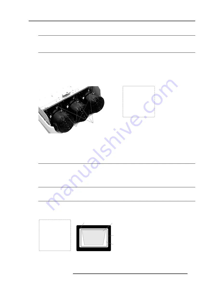
How to focus the lenses ?
Each lens has two focus adjustment points, one at the rear of the lens and one at the front. The center of the projected image is focused
by loosening the wing nut at the rear end of the lens and rotating the lens barrel until the center of the image is clearly focused. The
corners of the projected image are focused by loosening the wing nut at the front end of the lens and rotating the lens barrel until
the corners of the image are clearly focused. Repetition of these adjustments may be necessary to optimize optical focusing.
Press ENTER to continue. After finishing focusing of the three lenses, press ENTER to enter the Raster centering.
Press EXIT to return to operational mode.
Press ADJUST to return to operational mode.
Corner focusing
Center focusing
237,&$//(16)2&86,1*
<ENTER> to continue
<EXIT> to return
1. LOOSEN THE NUT ON THE
REAR OF THE GREEN LENS,
ROTATE THE LENS BARREL
TO FOCUS THE CENTER
OF THE IMAGE,
THEN TIGHTEN THE NUT
2. LOOSEN THE NUT ON THE
FRONT OF THE GREEN LENS
AND ROTATE THE FRONT
SECTION OF THE LENS TO
FOCUS THE CORNERS OF THE
IMAGE, THEN TIGHTEN THE NUT.
menu 3
menu 1
Raster Centering
What has to be done ?
The raster must be centered on the CRT faceplate of each tube, therefore, it is necessary to look into the lenses.
Caution : To avoid eye discomfort while performing these adjustments, reduce the contrast and gradually increase the brightness
level until the raster becomes visible behind the image.
Warning
In order to ensure maximum CRT longevity and to avoid CRT damage, do not shift the raster outside the phosphor area of the CRT.
How to adjust ?
Press ENTER to display the raster on the green CRT.
Look into the green lens and shift the raster with the cursor keys until it is centered in the middle of the CRT faceplate.
5$67(5&(17(5,1*
<ENTER> to continue
<EXIT> to return
CONTRAST LEVEL IS REDUCED
AND BRIGHTNESS INCREASED
TO MAKE THE RASTER
VISIBLE ON THE FACE PLATE
OF EACH CRT.
USE THE ARROW KEYS
TO CENTER THE RASTER
ON THE GREEN, RED AND
BLUE CRT RESPECTIVELY
Forbidden area
Projected raster
CRT faceplate border
Phosphor area
menu 1
Image 1


