


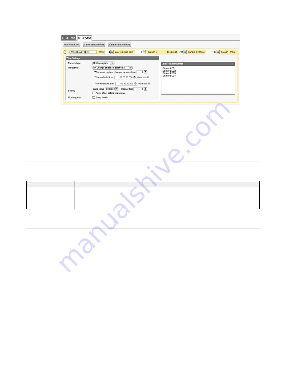
Figure 54. RTU Write rules
5. Save the XML configuration from the
File
>
Save As
menu.
6. Connect to the DXM using a USB cable and select
Device
>
Connection Settings
from the menu bar.
7. Upload the XML configuration file to the DXM by selecting
Device
>
Upload Configuration to Device
from the menu
bar.
After a configuration file is uploaded, the DXM reboots. The new configuration is now running.
Turning on any one of the universal inputs 1 through 4 on the I/O base board of the DXM now turns on an LED on the
display.
9.3 Using the Auxiliary Power Outputs
The DXM has two auxiliary power outputs, pin 35 and pin 45. They are controlled by hardware jumpers on the I/O base
board. Refer to the wiring board diagram for more information.
Table 54: Auxiliary power output pins
Pin
Description
Pin 35, Pin 45
The auxiliary power outputs are controlled by hardware jumpers (PWR Out jumper bank).
Jumper 2 is the power jumper for pin 45. Jumper 1 is the power jumper for pin 35.
•
The pin 45 jumper selects 2.7 V when in the "a" position and 12 V battery in the "b" position.
•
The pin 35 jumper selects 4.2 V when in the "a" position and device power on pin 2 in the "b" position.
9.4 Working with Solar Power
A reliable solar system requires careful planning and monitoring to size the components correctly. The recommendations
provided are for the DXM system as an autonomous system.
Adding extra components increases the power requirements and likely requires increasing the solar system components.
Depending upon the geographical location, the size of the solar panel and battery may vary.
9.4.1 Setting the DXM for Solar Power
By default, the DXM is set from the factory to charge a backup battery from a line power source.
For DXM models with an LCD, use the buttons and menu system to change the charging algorithm to solar power. Go to
System Config
>
I/O Board
>
Charger
. Use the up/down arrows to select
Solar
.
For DXM models without an LCD, use the configuration software to adjust the I/O board Modbus register 6071. Set the
register to 0 to select battery charging from a solar panel, and set to 1 to select battery charging from incoming 12 to 30 V DC
supply.
To minimize the power consumption (may not apply to all models):
•
If Ethernet is not being used, save up to 25% of the consumed power by disabling Ethernet. Set DIP switch 1 to the
ON position on the processor board then reboot.
•
Instead of powering external devices all the time, take advantage of the switched power mechanisms to turn off
devices when possible.
•
Minimize the number of cellular transactions and the amount of data pushed across the cellular modem.
Sure Cross
®
DXM150 and 1500-Bx Wireless Controllers
78
www.bannerengineering.com - Tel: + 1 888 373 6767


