background image

Installing the Fibers

Follow these steps to install glass or plastic fibers.

1. Open the dust cover.
2. Move the fiber clamp forward to unlock it.
3. Insert the fiber(s) into the fiber port(s) until they

stop.

4. Move the fiber clamp backward to lock the fiber(s).
5. Close the dust cover.

Fiber Emitter

Port

Fiber Receiver

Fiber Clamp

Port

Move forward

to release the

fibers

Fiber Adapters

NOTE: If a thin fiber with less than 2.2 mm outer diameter is used, install the fiber adapter provided

with the fiber assembly to ensure a reliable fit in the fiber holder. Banner includes the adapters with all

fiber assemblies.


TO

FIBERS

TO

SENSOR


Fiber Outer Diameter (mm)

Adapter Color

Ø 1.0

Black

Ø 1.3

Red

Ø 2.2

No adapter needed

When connecting coaxial-type fiber assemblies to the amplifier, install the single-core fiber to the Transmitter port, and the

multi-core fiber to the Receiver port. This will result in the most reliable detection.


TRANSMITTER

RECEIVER

Single-core fiber

Multi-core fiber


DF-G2 High Speed Expert

 Dual Display Small Object Counter


P/N 178061 Rev. E

www.bannerengineering.com - Tel: +1-763-544-3164

3

Summary of Contents for DF-G2 High Speed Expert

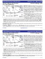
Page 1: ...vel 6 Green Threshold 7 SET Rocker Button Models Model Outputs Connector1 DF G2 NC 2M Single NPN plus Health Mode output 2 m 6 5 ft cable 5 wire DF G2 PC 2M Single PNP plus Health Mode output DF G2 NC...

Page 2: ...the DF G2 up on the DIN rail 1 3 Pivot the DF G2 onto the DIN rail pressing until it snaps into place 2 Mount to the Accessory Bracket 1 Position the DF G2 in the SA DIN BRACKET 2 Insert the supplied...

Page 3: ...nstall the fiber adapter provided with the fiber assembly to ensure a reliable fit in the fiber holder Banner includes the adapters with all fiber assemblies TO FIBERS TO SENSOR Fiber Outer Diameter m...

Page 4: ...output is ON when the sensing condition is above the threshold For Window SET the output is ON when the sensing condition is inside the window In Dark Operate mode the output is ON when the sensing co...

Page 5: ...counts value to reset to 0 Program Mode or to set value or to set value or to set value display flips 180 Click SET to enter choice list Press and hold SET to exit choice list without saving DISPLAY...

Page 6: ...ease decrease the window size A single sensing condition is presented and the sensor positions window thresholds a programmable offset above and below the presented condition In LO mode Window SET des...

Page 7: ...t OFF Output ON Darkest Taught Condition Lightest Taught Condition Position Figure 5 Dynamic TEACH Light Operate shown The output ON and OFF conditions can be reversed using the LO DO switch Troublesh...

Page 8: ...econds Return the system to normal operation by cleaning the fiber optic array and performing a Window SET to reset the clear state light level see Window SET on page 6 Specifications Sensing Beam Vis...

Page 9: ...warranty period This warranty does not cover damage or liability for misuse abuse or the improper application or installation of the Banner product THIS LIMITED WARRANTY IS EXCLUSIVE AND IN LIEU OF AL...

Reviews: