background image

SECTION 2.0 – QUICK START GUIDE

PAGE 5

SECTION 2.1 – Smartgauge INSTALLATION BASICS

SECTION 2.2 – IMPORTANT INSTALLATION NOTES

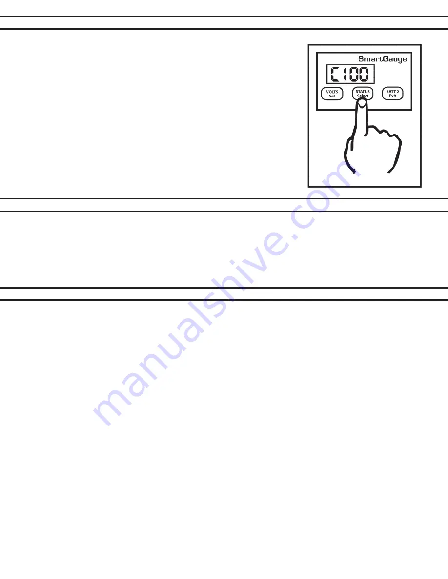
Pressing the STATUS button will display the charge status as a percentage. 

Initially, battery charge status will be shown at 75%. During the first run cycle, 

the Smartgauge™ will begin to synchronize itself. It will typically take two or 

three discharge and recharge cycles for the Smartgauge™ to “learn” to ac-

curately read your house battery’s State of Charge. Synchronization is not an 

instant effect. The Smartgauge™ will continue to track battery condition with 

increasing accuracy over time.
This completes installation and initial setup of Smartgauge™. For operation 

and details of further functions such as alarms, error codes, etc., refer to the 

main section of the owner’s manual.

The purpose of this manual is to enable the installer to install Smartgauge™ in a manner that permits it to  

operate as designed. This manual’s purpose is not to educate the installer on the legal requirements of any 

particular type of installation. The manufacturer, supplier, dealer and/or their agents cannot know what the final 

installation will be and therefore cannot know what the legal requirements of such installation may be.
Installation of Smartgauge™ is simple and should be completed in a short time. Only two wires are required to 

operate Smartgauge™ for normal single-bank system, with only three wires required for a dual-bank installation.

1.  The sense wire connected to the B1 terminal on the back of the Smartgauge

 must be connected to the 

house (primary) battery bank. The B2 terminal should be connected to the engine starting battery via the 

secondary sense wire.

2.  Both battery banks must be either 12 volts or 24 volts. The Smartgauge

 cannot be used in a mixed instal-

lation with 12-volt and 24-volt battery banks.

3.  Battery banks connected to the Smartgauge

 MUST share a common ground. It is not possible to install the 

Smartgauge on 2 isolated battery systems or on 2 battery systems with a common positive.

4.  Keep wire runs the between the Smartgauge

 and the batteries as short as possible. Use at least 16-gauge 

(AWG) wire for B1 sense, B2 sense and Negative (Ground) connections.

5.  B1 and B2 sense wires must be fused as near to the batteries as possible. A 3-amp ATC fuse is recom-

mended for each sense wire installed.

6.  Positive voltage sense and negative (ground) wires must be connected directly to the battery posts of the 

batteries being monitored. Connecting them to busses or other non-battery terminal connections could result 

in poor or inaccurate monitor performance. 

7.  Do not use positive sense wires or ground wires as power sources for other loads (like warning lights or au-

dible alarms. Doing so will affect Smartgauge

 accuracy. 

8.  If Smartgauge™ is replacing a shunt-based monitor or ammeter, do not connect the sense wires to the exist-

ing shunt. The sense wires MUST be connected directly to the batteries being monitored.

Summary of Contents for Smartgauge

Page 1: ...17 9 0 Addendum Page 17 10 0 Specifications Page 18 11 0 Warranty Page 19 12 0 Smartgauge Display Flowcharts Page 19 CONTENTS BALMAR LLC MARYSVILLE WA 98271 USA WWW BALMAR NET 1 360 435 6100 2016 Bal...

Page 2: ...t by the user the reading error will compound known as synchronization error In most battery monitors a shunt is used to monitor amperage in or out of the battery Unfortunately in many cases shunts ca...

Page 3: ...h or navigation area or in other locations where it can be easily accessed for viewing The rect angular display panel requires a rough opening measuring 3 75 wide by 2 55 tall as illustrated in Diagra...

Page 4: ...play will indicate the software and battery model revisions The Smartgauge will then show bt 1 in the display and the PGM Batt 2 LED will be flashing Use the STATUS button to scroll through the progra...

Page 5: ...ngle bank system with only three wires required for a dual bank installation 1 The sense wire connected to the B1 terminal on the back of the Smartgauge must be connected to the house primary battery...

Page 6: ...r details Pressing the STATUS button will scroll through the available battery types Pressing the VOLTS button will store the battery program you select based on your battery type The display will fla...

Page 7: ...tgauge is installed on a 24 volt system with extremely low battery volt age The low voltage could result in the Smartgauge determining that the system is a 12 volt system Alternately the Smartgauge co...

Page 8: ...nk display press VOLTS or STATUS If no buttons are activated for two minutes the display will go into sleep mode This is a power saving feature Smartgauge will continue to operate calculating the char...

Page 9: ...isplay modes etc will be displayed first Pressing the SET button will show each selected item without ever changing any of them This allows you to look through the menu to check all the settings witho...

Page 10: ...alue to memory then exit the set up menu There are two levels of alarm settings in Smartgauge The first is the Primary Alarm which can be set OFF or can be used to access low high voltage or low SoC f...

Page 11: ...he set up menu Clarification For a low voltage alarm 1 The battery voltage has to fall below the activation voltage to trigger the alarm 2 The battery voltage has to rise to the deactivation voltage t...

Page 12: ...x indicating the time in hours and minutes that the alarm will remain activated The default is 4 hours However if an alarm of this type is actually active when you enter the set up menu i e the alarm...

Page 13: ...ed battery type will activate the alarm output Note that if error codes are disabled the next function in the set up menu this secondary alarm will not operate Range Error code E04 measurement range e...

Page 14: ...tes later Note that whilst this setting uses the upper deactivation voltage level of the low voltage alarm the low voltage alarm does not have to be enabled or ac tive for this function to operate The...

Page 15: ...o clear the error code simply press any button If another error occurs while an earlier error is displayed the new error code will take precedence The exception to this is the unique case of an E01 lo...

Page 16: ...if these limits are exceeded there is something seriously wrong with the installation Such extreme voltages simply should not arise and indicates a serious problem with the charging system HI Battery...

Page 17: ...e alarm output deactivates COM is once again connected to NC and NO is connected to nothing The alarm LED will go off again The sounder will go silent Operation of the standard low status alarm is ide...

Page 18: ...using the Primary Alarm set to operate on charge status If this is being used to operate an auto start generator and charger and the generator is regularly shut down before reaching 100 charge status...

Page 19: ...isit www balmar net for more information regarding Balmar warranty policies and procedures PAGE 19 SECTION 12 0 SMARTGAUGE FLOW CHARTS 12 1 DisplayMode First Time Power Up Following Factory Reset r 1...

Page 20: ...2 65 bt x db x C X X PA 0 EC 0 EC 1 Loc 0 12 65 Loc 1 dt t dt A dt U SA U SA r SA P SA A PA U 11 8 13 3 HI LO PA S C 50 C 95 C 50 T1 45 PA T C 76 NORMAL OPERATIO N NORMAL OPERATIO N VOLTS BUTTO N STAT...

Reviews: