background image

If a low voltage alarm was set, the lower voltage trip point is the 

voltage below which the actual battery voltage will have to fall in 

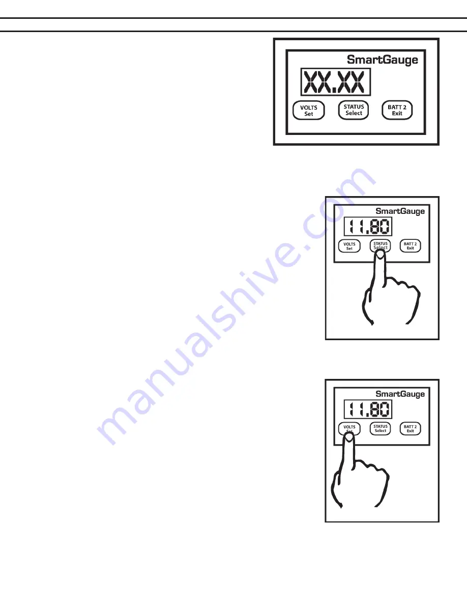
order to trigger (activate) the alarm output. This is the activation 

voltage. The factory default for this value is 11.80 volts. Press-

ing the SELECT button will scroll this value up to and including 

16.50 volts. It will then cycle to 10.50 volts then continue to scroll 

upwards. When the desired value is displayed, press the SET 

button to write the value to memory, the display will flash. The 

upper voltage trip point is the voltage which the actual battery 

voltage will have to rise to in order to deactivate the alarm. This 

is the deactivation voltage. The factory default for this is 13.20 

volts. Pressing the Select button will scroll this value up to 16.50 

volts, it will then wrap round to whatever value was previously entered for the alarm activation voltage. This 

means that no matter what you do, Smartgauge™ will not allow this value to be set lower than the activation 

voltage. 
Pressing the SET button will write the value to memory. If a high voltage alarm 

was  set  then  the  procedure  remains  identical  except  the  upper  voltage  trip 

point is the voltage which the battery voltage will have to rise to in order to acti-

vate the alarm. Once the alarm is triggered, the battery voltage will have to fall 

back down below the lower voltage trip point in order to deactivate the alarm. 
The display will then move on to the next item in the set-up menu, secondary 

alarms. Remember, at any time in the set-up menu, pressing the EXIT button 

will write the current value to memory then exit the set-up menu. 
Clarification – For a low voltage alarm: 
1.  The battery voltage has to fall below the activation voltage to trigger the 

alarm.

2.  The battery voltage has to rise to the deactivation voltage to kill the alarm.
So if the activation voltage is set to 12.00 volts then the battery voltage will 

have to fall to 11.99 volts to trigger the alarm. If the deactivation voltage is set 

to 12.80 volts then the battery voltage will have to rise to 12.80 to cancel the alarm. Although the battery voltage 

is displayed to a resolution of 0.05 volts (0.1 volts in 24 volt systems), internally it is measured and dealt with to 

a finer resolution.
While  16.50  volts  may  seem  very  high  for  a  maximum  low  voltage  setting, 

this does allow the low voltage alarm to be used for two extra functions. One 

is as a “charger failure” alarm, the other is to enable the feature to be used to 

auto-start a generator set feeding a constant current type battery charger and 

shutting the generator down at the correct time.
For a high voltage alarm:-
1.  The battery voltage has to rise to the deactivation voltage to trigger the 

alarm.

2.  The battery voltage has to fall below the activation voltage to kill the alarm.

Status Alarm

There are two types of Low-Status alarms. The first is exactly the same as 

the low-voltage alarm but operates on charge status instead of on battery  

voltage. So the alarm will activate once the charge status falls below the chosen  

activation status, and will deactivate after the charge status rises back up to the chosen deactivation status. This 

type is designated in the display as “PA S”
The “PA S” type alarm is set in exactly the same way as the “PA U” alarm except “PA S” is selected instead of “PA 

U”. i.e. the activation status will be set, followed by the deactivation status.

PAGE 11

SECTION 4.4 – SET UP MODE – 

ALARM FUNCTIONS

Summary of Contents for Smartgauge

Page 1: ...17 9 0 Addendum Page 17 10 0 Specifications Page 18 11 0 Warranty Page 19 12 0 Smartgauge Display Flowcharts Page 19 CONTENTS BALMAR LLC MARYSVILLE WA 98271 USA WWW BALMAR NET 1 360 435 6100 2016 Bal...

Page 2: ...t by the user the reading error will compound known as synchronization error In most battery monitors a shunt is used to monitor amperage in or out of the battery Unfortunately in many cases shunts ca...

Page 3: ...h or navigation area or in other locations where it can be easily accessed for viewing The rect angular display panel requires a rough opening measuring 3 75 wide by 2 55 tall as illustrated in Diagra...

Page 4: ...play will indicate the software and battery model revisions The Smartgauge will then show bt 1 in the display and the PGM Batt 2 LED will be flashing Use the STATUS button to scroll through the progra...

Page 5: ...ngle bank system with only three wires required for a dual bank installation 1 The sense wire connected to the B1 terminal on the back of the Smartgauge must be connected to the house primary battery...

Page 6: ...r details Pressing the STATUS button will scroll through the available battery types Pressing the VOLTS button will store the battery program you select based on your battery type The display will fla...

Page 7: ...tgauge is installed on a 24 volt system with extremely low battery volt age The low voltage could result in the Smartgauge determining that the system is a 12 volt system Alternately the Smartgauge co...

Page 8: ...nk display press VOLTS or STATUS If no buttons are activated for two minutes the display will go into sleep mode This is a power saving feature Smartgauge will continue to operate calculating the char...

Page 9: ...isplay modes etc will be displayed first Pressing the SET button will show each selected item without ever changing any of them This allows you to look through the menu to check all the settings witho...

Page 10: ...alue to memory then exit the set up menu There are two levels of alarm settings in Smartgauge The first is the Primary Alarm which can be set OFF or can be used to access low high voltage or low SoC f...

Page 11: ...he set up menu Clarification For a low voltage alarm 1 The battery voltage has to fall below the activation voltage to trigger the alarm 2 The battery voltage has to rise to the deactivation voltage t...

Page 12: ...x indicating the time in hours and minutes that the alarm will remain activated The default is 4 hours However if an alarm of this type is actually active when you enter the set up menu i e the alarm...

Page 13: ...ed battery type will activate the alarm output Note that if error codes are disabled the next function in the set up menu this secondary alarm will not operate Range Error code E04 measurement range e...

Page 14: ...tes later Note that whilst this setting uses the upper deactivation voltage level of the low voltage alarm the low voltage alarm does not have to be enabled or ac tive for this function to operate The...

Page 15: ...o clear the error code simply press any button If another error occurs while an earlier error is displayed the new error code will take precedence The exception to this is the unique case of an E01 lo...

Page 16: ...if these limits are exceeded there is something seriously wrong with the installation Such extreme voltages simply should not arise and indicates a serious problem with the charging system HI Battery...

Page 17: ...e alarm output deactivates COM is once again connected to NC and NO is connected to nothing The alarm LED will go off again The sounder will go silent Operation of the standard low status alarm is ide...

Page 18: ...using the Primary Alarm set to operate on charge status If this is being used to operate an auto start generator and charger and the generator is regularly shut down before reaching 100 charge status...

Page 19: ...isit www balmar net for more information regarding Balmar warranty policies and procedures PAGE 19 SECTION 12 0 SMARTGAUGE FLOW CHARTS 12 1 DisplayMode First Time Power Up Following Factory Reset r 1...

Page 20: ...2 65 bt x db x C X X PA 0 EC 0 EC 1 Loc 0 12 65 Loc 1 dt t dt A dt U SA U SA r SA P SA A PA U 11 8 13 3 HI LO PA S C 50 C 95 C 50 T1 45 PA T C 76 NORMAL OPERATIO N NORMAL OPERATIO N VOLTS BUTTO N STAT...

Reviews: