background image

PAGE 14

SECTION 4.5 – SET UP MODE – 

DEFEATING ERROR CODES

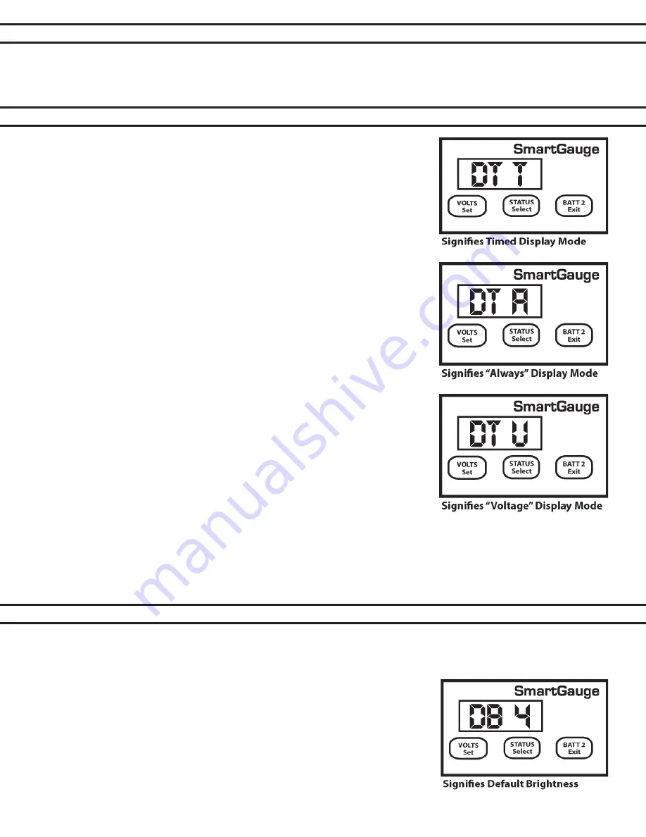
There are three display modes available in the Smartgauge™. The modes 

apply whether the display is showing volts or charge status.
The default factory setting displays for 2 minutes before going into sleep 

mode. This mode is signified in the set-up menu as “dt t” meaning display 

type = timed. This display will remain active for 2 minutes following a button 

press. It will then go back to sleep. Pressing a button will switch the display 

back on for another 2 minutes.
The second display mode is “dt A” meaning “display type = Always” where the 

display will always be on and will never go into sleep mode.
The third display mode is “dt U” meaning “display type = Voltage” where the 

display will go into sleep mode, after 2 minutes, as usual, below a certain volt- 

age but will always remain on above a certain voltage. This voltage is actually 

the upper voltage trip point for the high/low voltage alarm. The factory default 

setting for this is 13.20 volts (26.40 volts on 24 volt systems). So if this dis- 

play mode (“dt U”) is selected and the alarm factory defaults have not been 

adjusted, the display will blank as normal after 2 minutes if the battery voltage 

is below this level but will always be on above this voltage. This makes sense 

in so far as if the battery voltage is above this level then clearly the batteries 

are either being charged or they are well charged and in either case the extra 

few milliamps of power consumed is not an issue. It also allows a keen eye to 

keep watch on the battery charge voltage without having to continually press 

buttons. But when the charger is switched off Smartgauge™ will revert to the 

minimum required current draw by blanking the display 2 minutes later.
Note that whilst this setting uses the upper deactivation voltage level of the 

low voltage alarm, the low voltage alarm does not have to be enabled or 

ac- tive for this function to operate. The two functions merely share the same 

value.
To select the display mode, enter the set-up menu as usual, then press the VOLTS button until “dt x” is displayed. 

“dt” signifying display type, the x showing either t, A or U. Now press the STATUS button to scroll through the 

three or four values. Press VOLTS to confirm the choice. The display will flash to show the value has been written 

to memory. The display will then move onto the next menu item.

SECTION 4.6 – SET UP MODE – 

DISPLAY BEHAVIOR

SECTION 4.7 – SET UP MODE – 

DISPLAY BRIGHTNESS

If the “Secondary Alarm” function has been set to activate the alarm on E 02 or E 03, or set to activate the alarm 

on all error codes, and E 02 and E 03 have been disabled then they will no longer trigger the alarm. The remain-

ing error codes will still activate the alarm as programmed. 

The display brightness is fully adjustable to enable the Smartgauge™ to be used in any light conditions. One 

of the advantages of this type of display (LED – Light Emitting Diode) as opposed to the other common display 

(LCD – Liquid Crystal Display) is that they can be read in zero light conditions as well as daylight. To adjust the 

display  brightness  enter  the  set-up  menu,  then  press  the  VOLTS  key  until 

“db x” is displayed. “db” signifies display brightness, x indicates the current  

brightness which will be from 1 to 8. The factory default value is 4.  

Pressing the STATUS button will scroll through the values, cycling to 1 when 

8 is reached. You will see the brightness change as you scroll through the 

values. When you find the brightness level that best suits your environment, 

press the VOLTS button. The display will flash to show the value has been 

stored then Smartgauge™ will move on to the final item in the set-up menu.
 

Summary of Contents for Smartgauge

Page 1: ...17 9 0 Addendum Page 17 10 0 Specifications Page 18 11 0 Warranty Page 19 12 0 Smartgauge Display Flowcharts Page 19 CONTENTS BALMAR LLC MARYSVILLE WA 98271 USA WWW BALMAR NET 1 360 435 6100 2016 Bal...

Page 2: ...t by the user the reading error will compound known as synchronization error In most battery monitors a shunt is used to monitor amperage in or out of the battery Unfortunately in many cases shunts ca...

Page 3: ...h or navigation area or in other locations where it can be easily accessed for viewing The rect angular display panel requires a rough opening measuring 3 75 wide by 2 55 tall as illustrated in Diagra...

Page 4: ...play will indicate the software and battery model revisions The Smartgauge will then show bt 1 in the display and the PGM Batt 2 LED will be flashing Use the STATUS button to scroll through the progra...

Page 5: ...ngle bank system with only three wires required for a dual bank installation 1 The sense wire connected to the B1 terminal on the back of the Smartgauge must be connected to the house primary battery...

Page 6: ...r details Pressing the STATUS button will scroll through the available battery types Pressing the VOLTS button will store the battery program you select based on your battery type The display will fla...

Page 7: ...tgauge is installed on a 24 volt system with extremely low battery volt age The low voltage could result in the Smartgauge determining that the system is a 12 volt system Alternately the Smartgauge co...

Page 8: ...nk display press VOLTS or STATUS If no buttons are activated for two minutes the display will go into sleep mode This is a power saving feature Smartgauge will continue to operate calculating the char...

Page 9: ...isplay modes etc will be displayed first Pressing the SET button will show each selected item without ever changing any of them This allows you to look through the menu to check all the settings witho...

Page 10: ...alue to memory then exit the set up menu There are two levels of alarm settings in Smartgauge The first is the Primary Alarm which can be set OFF or can be used to access low high voltage or low SoC f...

Page 11: ...he set up menu Clarification For a low voltage alarm 1 The battery voltage has to fall below the activation voltage to trigger the alarm 2 The battery voltage has to rise to the deactivation voltage t...

Page 12: ...x indicating the time in hours and minutes that the alarm will remain activated The default is 4 hours However if an alarm of this type is actually active when you enter the set up menu i e the alarm...

Page 13: ...ed battery type will activate the alarm output Note that if error codes are disabled the next function in the set up menu this secondary alarm will not operate Range Error code E04 measurement range e...

Page 14: ...tes later Note that whilst this setting uses the upper deactivation voltage level of the low voltage alarm the low voltage alarm does not have to be enabled or ac tive for this function to operate The...

Page 15: ...o clear the error code simply press any button If another error occurs while an earlier error is displayed the new error code will take precedence The exception to this is the unique case of an E01 lo...

Page 16: ...if these limits are exceeded there is something seriously wrong with the installation Such extreme voltages simply should not arise and indicates a serious problem with the charging system HI Battery...

Page 17: ...e alarm output deactivates COM is once again connected to NC and NO is connected to nothing The alarm LED will go off again The sounder will go silent Operation of the standard low status alarm is ide...

Page 18: ...using the Primary Alarm set to operate on charge status If this is being used to operate an auto start generator and charger and the generator is regularly shut down before reaching 100 charge status...

Page 19: ...isit www balmar net for more information regarding Balmar warranty policies and procedures PAGE 19 SECTION 12 0 SMARTGAUGE FLOW CHARTS 12 1 DisplayMode First Time Power Up Following Factory Reset r 1...

Page 20: ...2 65 bt x db x C X X PA 0 EC 0 EC 1 Loc 0 12 65 Loc 1 dt t dt A dt U SA U SA r SA P SA A PA U 11 8 13 3 HI LO PA S C 50 C 95 C 50 T1 45 PA T C 76 NORMAL OPERATIO N NORMAL OPERATIO N VOLTS BUTTO N STAT...

Reviews: