background image

PAGE 12

SECTION 4.4 – SET UP MODE – 

ALARM FUNCTIONS


Clarification:
1.  The SoC% has to fall below the activation status to trigger the alarm.
2.  The SoC% has to rise to the deactivation status to kill the alarm. The range limits are: 

1. Activation status = 1 to 75% 
2. Deactivation status = activation status to 100%

Factory defaults are activation status = 50%, deactivation status = 95%. These would be typical figures used for 

an auto start gen-set (See Note 2 in addendum for additional information).
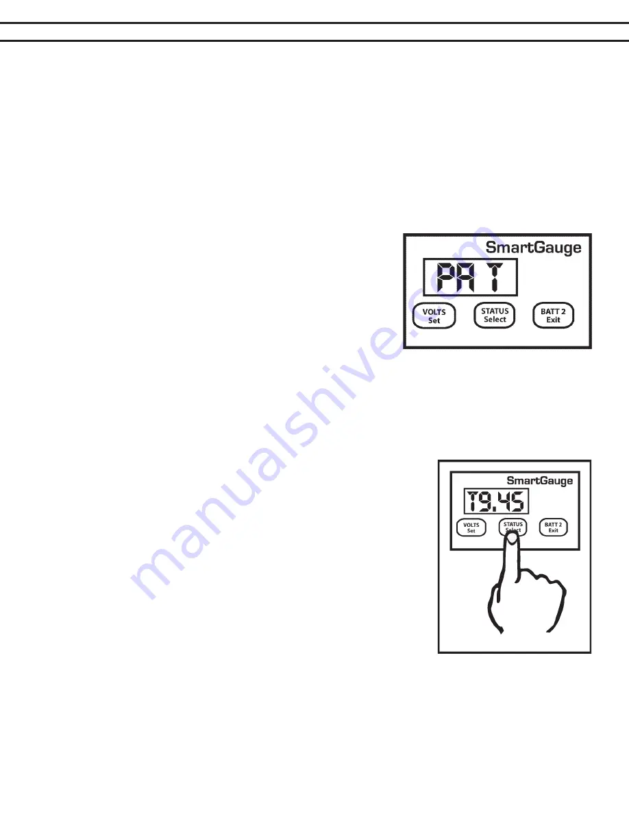
The “PA t” alarm is slightly different. If this alarm is set, the alarm will trigger (be activated) once the charge sta-

tus falls below the activation status. The alarm will remain triggered until the status rises back up to the same 

activation level but then, once this happens, a timer is started which counts down from the set time period, and 

when it reaches zero, the alarm is deactivated. The main reason for this 

type of alarm is to enable an auto start generator set to be started once 

the charge status falls to a certain level and then run for a certain fixed 

period (see Note 2 in addendum). 
On selecting “PA t” the display will flash  to show the value was written 

to memory. The display will then show “xx” which is the charge status 

below which the actual battery charge status will have to fall in order to 

trigger (activate) the alarm output. This is the activation status. The fac-

tory default for this value is 50%. Pressing the SELECT button will scroll 

this value up to and including 75%. It will then cycle to 1 and continue to 

scroll upwards. When the desired value is displayed, press the SET button to write the value to memory, the dis-

play will flash as usual. The activation status is now set. Note that this activation status shares the same memory 

as that used for the normal low status alarm. So changing one, will change the other.
The display will now show “tx.xx”, indicating the time, in hours  and minutes, that the alarm will remain activated. 

The default is 4 hours. However, if an alarm of this type is actually active when you enter the set-up menu (i.e. 

the alarm LED is on), then this figure will be the current time remaining, on the current countdown timer, rounded 

to the nearest 15 minutes. This enables the user to increase or decrease the 

remaining time for an existing alarm timer run. 
Pressing the SELECT button will increase this time in steps of 15 minutes up 

to a maximum of 9 hours and 45 minutes and cycle back to 15 minutes. Once 

the desired time is reached, pressing the SET button will, as usual, cause the 

display to flash, the value will be written to memory and the display will move 

on to the next item in the set-up menu. 
If an alarm is not active at the time you enter the set-up menu then this time 

period will become the default time period for all future status timed alarms. 

Remember, changing alarm type will cancel any currently active alarms. If this 

menu item is entered while a timed alarm run is active and it shows the time re-

maining on the current run (as opposed to your default run time), only the time 

remaining on the current run will be affected. 
The normal full time for a timed alarm run will not be changed and will remain 

as you last set it (or at the factory default if no changes have been made). It 

is not possible to change the default run time whilst a timed alarm run is active. Note that this timed period is 

approximate. The timed period and the display will be accurate to within about 10% Also note that internally  

Smartgauge™ counts in seconds whereas the display only shows the minutes. It is rounded to the nearest min-

ute so when the display counts down and reaches zero, there could in fact be 30 seconds remaining. 

Set-up mode - Alarms – General

Once an alarm is triggered, the alarm output will activate. The Alarm LED on the front panel will illuminate and 

the display will alternate between its current display (for 3 seconds) and the alarm display (for 1 second). The 

Summary of Contents for Smartgauge

Page 1: ...17 9 0 Addendum Page 17 10 0 Specifications Page 18 11 0 Warranty Page 19 12 0 Smartgauge Display Flowcharts Page 19 CONTENTS BALMAR LLC MARYSVILLE WA 98271 USA WWW BALMAR NET 1 360 435 6100 2016 Bal...

Page 2: ...t by the user the reading error will compound known as synchronization error In most battery monitors a shunt is used to monitor amperage in or out of the battery Unfortunately in many cases shunts ca...

Page 3: ...h or navigation area or in other locations where it can be easily accessed for viewing The rect angular display panel requires a rough opening measuring 3 75 wide by 2 55 tall as illustrated in Diagra...

Page 4: ...play will indicate the software and battery model revisions The Smartgauge will then show bt 1 in the display and the PGM Batt 2 LED will be flashing Use the STATUS button to scroll through the progra...

Page 5: ...ngle bank system with only three wires required for a dual bank installation 1 The sense wire connected to the B1 terminal on the back of the Smartgauge must be connected to the house primary battery...

Page 6: ...r details Pressing the STATUS button will scroll through the available battery types Pressing the VOLTS button will store the battery program you select based on your battery type The display will fla...

Page 7: ...tgauge is installed on a 24 volt system with extremely low battery volt age The low voltage could result in the Smartgauge determining that the system is a 12 volt system Alternately the Smartgauge co...

Page 8: ...nk display press VOLTS or STATUS If no buttons are activated for two minutes the display will go into sleep mode This is a power saving feature Smartgauge will continue to operate calculating the char...

Page 9: ...isplay modes etc will be displayed first Pressing the SET button will show each selected item without ever changing any of them This allows you to look through the menu to check all the settings witho...

Page 10: ...alue to memory then exit the set up menu There are two levels of alarm settings in Smartgauge The first is the Primary Alarm which can be set OFF or can be used to access low high voltage or low SoC f...

Page 11: ...he set up menu Clarification For a low voltage alarm 1 The battery voltage has to fall below the activation voltage to trigger the alarm 2 The battery voltage has to rise to the deactivation voltage t...

Page 12: ...x indicating the time in hours and minutes that the alarm will remain activated The default is 4 hours However if an alarm of this type is actually active when you enter the set up menu i e the alarm...

Page 13: ...ed battery type will activate the alarm output Note that if error codes are disabled the next function in the set up menu this secondary alarm will not operate Range Error code E04 measurement range e...

Page 14: ...tes later Note that whilst this setting uses the upper deactivation voltage level of the low voltage alarm the low voltage alarm does not have to be enabled or ac tive for this function to operate The...

Page 15: ...o clear the error code simply press any button If another error occurs while an earlier error is displayed the new error code will take precedence The exception to this is the unique case of an E01 lo...

Page 16: ...if these limits are exceeded there is something seriously wrong with the installation Such extreme voltages simply should not arise and indicates a serious problem with the charging system HI Battery...

Page 17: ...e alarm output deactivates COM is once again connected to NC and NO is connected to nothing The alarm LED will go off again The sounder will go silent Operation of the standard low status alarm is ide...

Page 18: ...using the Primary Alarm set to operate on charge status If this is being used to operate an auto start generator and charger and the generator is regularly shut down before reaching 100 charge status...

Page 19: ...isit www balmar net for more information regarding Balmar warranty policies and procedures PAGE 19 SECTION 12 0 SMARTGAUGE FLOW CHARTS 12 1 DisplayMode First Time Power Up Following Factory Reset r 1...

Page 20: ...2 65 bt x db x C X X PA 0 EC 0 EC 1 Loc 0 12 65 Loc 1 dt t dt A dt U SA U SA r SA P SA A PA U 11 8 13 3 HI LO PA S C 50 C 95 C 50 T1 45 PA T C 76 NORMAL OPERATIO N NORMAL OPERATIO N VOLTS BUTTO N STAT...

Reviews: