


7-20 Parameter Descriptions
MN766
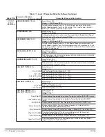
Block Title
Parameter (Number)
Selection (Value)
Parameter Name and Description
MISCELLA-
NEOUS
(Continued)
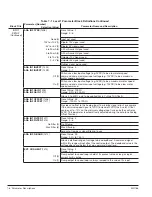
HOMING SPEED
(2307)
Preset Value: 90
Range: 0 - MAX Speed RPM
This parameter sets the speed that the motor shaft will rotate in the forward
direction to “Home” position when the home input switch is closed.
Available only in modes that have a homing (orient) input. For Bipolar and
Network Modes, the speed and ramp rates during this fi nal positioning are
set by Preset Speed 1 and ACC/DEC Group 2 respectively.
HOMING OFFSET
(2308)
Preset Value: 1024
Range: -9999 to 20000 counts (Range shown is limited by keypad display.
Value in MINT is -20000 to 20000).
This parameter sets the number of feedback counts past home at which the
motor will stop. Feedback pulses are 4 times the number of feedback lines
per revolution. The recommended minimum number is 100 feedback counts
to allow for deceleration distance to allow the motor to stop smoothly.
Example: The motor must stop one complete revolution past the home
marker position. Note: Homing direction always begins in the drive forward
direction. The shaft will continue to rotate in either direction to the user
defi ned ±offset value (P2308).
FILTER TYPE
(2309)
Preset Value: 0
Range: 0 - 3
None (0)
Sets the auxiliary fi lter to None.
Low Pass (1)
Sets the auxiliary fi lter to Low Pass.
High Pass (2)
Sets the auxiliary fi lter to High Pass.
Notch (3)
Sets the auxiliary fi lter to Notch.
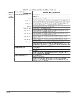
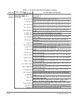
FILTER SOURCE
(2310)
Preset Value: 0
Range: 0 - 9
None (0)
Sets the auxiliary fi lter to None.
Raw Speed (1)
Sets the auxiliary fi lter to Raw Speed.
Torque (2)
Sets the auxiliary fi lter to Torque Loop.
Analog In1 (3)
Sets the auxiliary fi lter to Analog In1.
Analog In2 (4)
Sets the auxiliary fi lter to Analog In2.
Composite Ref (5)
Sets the auxiliary fi lter to Composite Reference.
Opt1 Ana In1 (6)
Sets the auxiliary fi lter to Opt1 Ana In1.
Opt1 Ana In2 (7)
Sets the auxiliary fi lter to Opt1 Ana In2.
Opt2 Ana In1 (8)
Sets the auxiliary fi lter to Opt2 Ana In1.
Opt2 Ana In2 (9)
Sets the auxiliary fi lter to Opt2 Ana In2.
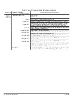
FILTER DEST
(2311)
Preset Value: 0
Range: 0 - 6
None (0)
Sets the Filter Destination, (Output), to None.
Speed Loop (1)
Sets the Filter Destination, (Output), to Speed Loop.
Torque Loop (2)
Sets the Filter Destination, (Output), to Torque Loop.
Speed FFWD (3)
Sets the Filter Destination, (Output), to Speed Forward.
Process FBK (4)
Sets the Filter Destination, (Output), to Process Feedback.
Process FFWD (5)
Sets the Filter Destination, (Output), to Process Feedforward.
Process SP (6)
Sets the Filter Destination, (Output), to Process Setpoint.
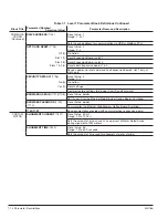
FILTER CUTOFF
(2312)
Preset Value: 0.00
Range: 0.00 - 1000.00Hz
Sets the cutoff frequency of the auxiliary fi lter (a low value = slower
response).
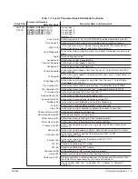
Table 7-2 Level 2 Parameter Block Defi nitions Continued
Summary of Contents for VS1SD
Page 1: ...05 13 Installation Operating Manual MN766 VS1SD AC Servo Control...
Page 12: ...2 2 General Information MN766...
Page 16: ...3 4 Installing the Drive MN766...
Page 108: ...7 34 Parameter Descriptions MN766...
Page 114: ...8 6 Customizing Your Application MN766...
Page 128: ...9 14 Troubleshooting MN766...
Page 154: ...12 12 Monitor and RTC Description MN766...


